• Keep the antenna line far away from power supply lines.
• Keep the antenna line far away from GSM RF lines.
• If there are noisy EM devices around the PCB hosting the module, such as fast
switching ICs, take care of the antenna line shielding by burying it inside the PCB
layers and surround it with Ground planes, or shield it with a metal frame cover.
• If there are not noisy EM devices around the PCB hosting the module, use a strip-
line on the superficial copper layer for the antenna line. The line attenuation will
be lower than a buried one.
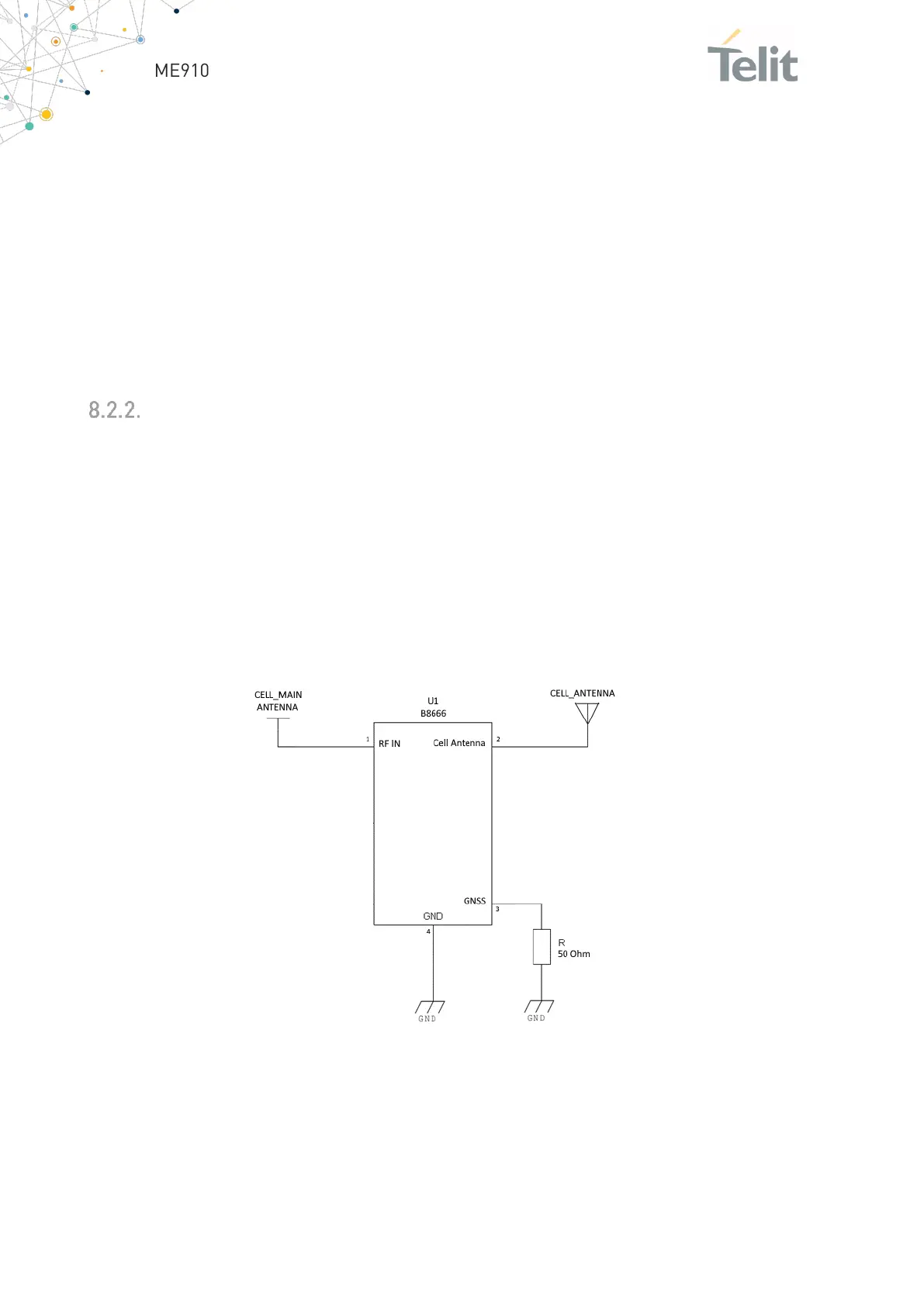
Hardware-based Solution for GNSS and LTE Coexistence
When a stand-alone GNSS receiver is present in the user application, the LTE
transmission may desensitize the GNSS receiver, in particular if the decoupling between
the LTE and GNSS antennas is low. A SAW filter can be added on LTE side, to protect the
GNSS receiver from LTE out-of-band emissions, as described in the schematic below.
When using the GNSS receiver embedded in the ME910G1 module, there is no
degradation condition, as the LTE part and the GNSS part are never active at the same
time, so there is no need for filtering on the LTE side.
Figure 22: Reference schematic

 Loading...


