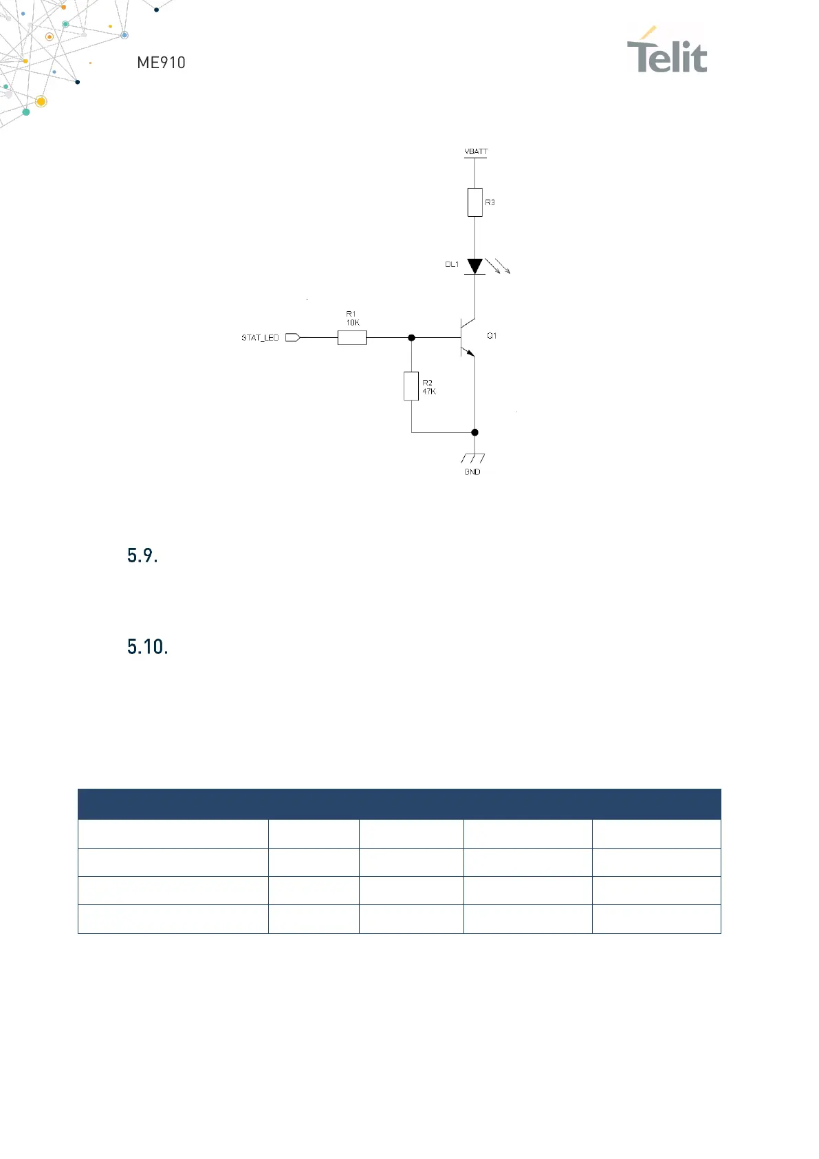
In the following reference schematic for LED indicator, R3 must be calculated taking in
account VBATT value and LED type:
Figure 16: LED indicator reference schematic
External SIM Holder
Please refer to the related User Guide (SIM Holder Design Guides, 80000NT10001a).
ADC Converter
The ME910G1 is includes one AD converter. It can read a voltage level in the range of
0÷1.8 volts applied on the ADC pin input, store it and convert it into 10 bit word.
The input line is named as ADC_IN1 and it is available on Pad B1
The following table is showing the ADC characteristics:
Table 26: ADC characteristics
The ADC could be controlled using an AT command.
The command is
AT#ADC=1,2
The read value is expressed in mV

 Loading...


