V1.1-OCTOBER 2019
| 45
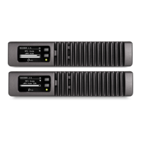
OMNIA MPX NODE MANUAL
There are two options for wiring up the GPIO connector.
1. Using the internal +5v and ground connections. Note that you will need to add jump-
ers between pins 1&2 and 14&15 on the GPIO connector
2. Using an external 5v power supply and its ground reference in place of the above
jumpers. This option isolates the ground planes and 5v power rail from transients
(such as EMP from a lightning hit).
The pins have internal pull-up resistors, so there is normally no need to select +5v for a
high unless a change is needed to “High” from the default state.
NET1
The NET1 Ethernet port provides 10/100/1000 connectivity. It is intended as the prima-
ry MPX over IP connection, and should be used as the default connection for users only
plugging a single network cable into the unit. As previously noted, a Gateway can be set
only for the NET1 port.
NET2
The NET2 Ethernet port provides 10/100 IP connectivity. It is primarily intended as a
control / admin port, but may be used to send / receive MPX over IP as well. Integrated
LED’s indicate connection and network activity for both network ports.
12VDC Input
An external 12 volt power, 5 amp power brick with locking barrel connector (Telos Part#
1771-00112-100) is included. When inserting the male connector into the rear panel
port, turn the locking ring counter-clockwise over the connector’s threads to secure it in
place.
Call-outs on the rear panel indicate where the MAC #1, #2 and Serial Number labels are
placed. These numbers are generated during the manufacturing process, and identify
the unique MAC addresses and unit serial numbers of each MPX Node. It should be
noted that separate serial number series are assigned for Encoders vs Decoders at time of
manufacturing, even though the base hardware is the same, and may be changed through
an internal DIP-switch.