V1.1-OCTOBER 2019
| 34
OMNIA MPX NODE MANUAL
10 Decoder Setup
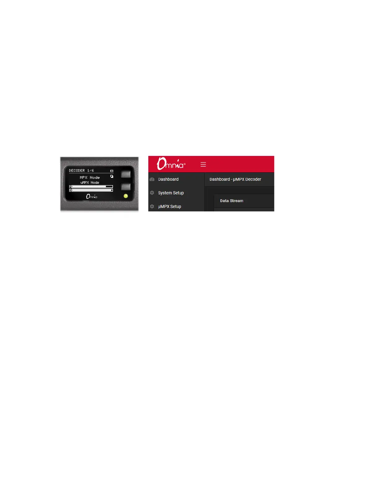
Verify your MPX Node is setup to run as a Decoder by checking the front panel display, or
the Dashboard display in the GUI. The word “Decoder” will be prominent, as below.
µMPX (MicroMPX) Decoder Settings
Internal switches are configured at the factory to set your MPX Node to encoder or decod-
er mode. Switch settings are detected on power up, and the encoder or decoder interface
is displayed accordingly. In decoder mode, the BNC connector on the rear panel acts as
an FM composite output. To decode a signal, feed it a μMPX stream over IP, then feed
your FM transmitter with the analog composite signal on the BNC connector. MPX Node
operates at standard levels: 3.5V peak-to-peak, low impedance.
The MPX Node decoder receives unicast traffic using UDP. An inbound μMPX signal
must be pointed at the IP address assigned to the MPX Node. Port 8854 is the default
port, which can be changed in the μMPX Setup screen. Inbound signals must be properly
port-forwarded, and firewalls set accordingly so this traffic can reach the unit. Multiple
streams can be pointed at a single decoder (including the same program on two streams
for redundancy), and the port being listened to can be changed from the GUI or via GPI.