8.17.4.2 Digital galvanically isolated input
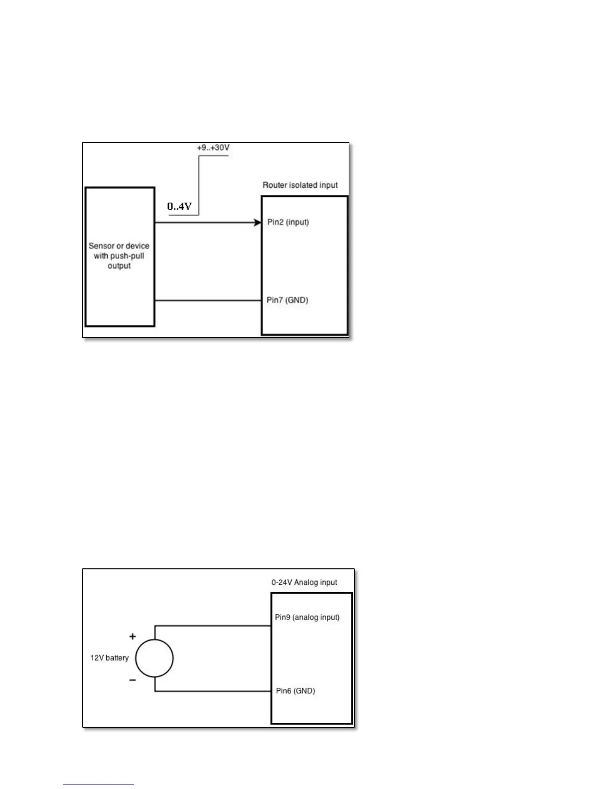
Sensors with push-pull output stage can be connected to this input. Example of such circuit is shown in the
picture below. The circuit uses optocoupler to isolate the input. In case of the failure at the input, the rest of the circuit
remains safe.
The signal source resistance should be less than 100Ω.
Input voltage levels:
• Low level voltage: 0..+4V
• High level voltage: +9..30V
Maximum ratings:
• Maximum voltage that can be connected to pin2 with respect to pin7 is 30V. Do not exceed this voltage!
• The input is protected from reverse voltage down to -200V.
8.17.4.3 Analog input
Analog input is designed to measure analog voltages in the range of 0-24V and convert it to digital domain.
Example of monitoring 12V battery voltage:
144
 Loading...