EasyManuals Logo

Teltonika RUT9 Series User Manual

Teltonika RUT9 Series
163 pages
To Next Page IconTo Next Page
To Previous Page IconTo Previous Page
Page #145 background imageLoading...
Page #145 background image
Input electrical characteristics:
Parameter
Value
Maximum voltage
24V
Minimum voltage
0V
Resolution
5.859mV
Input low-pass filter cut-off frequency (-3dB)
10Hz
Input resistance (seen between I/O header pins 9 and 6 )
131k
Input accuracy:
Input voltage range, V
Measurement error, %
0 <Vin≤ 1
<20
1 <Vin≤ 2
<10
2 <Vin≤ 5
<5
5 <Vin≤ 10
<1
10 <Vin≤ 24
<0.5
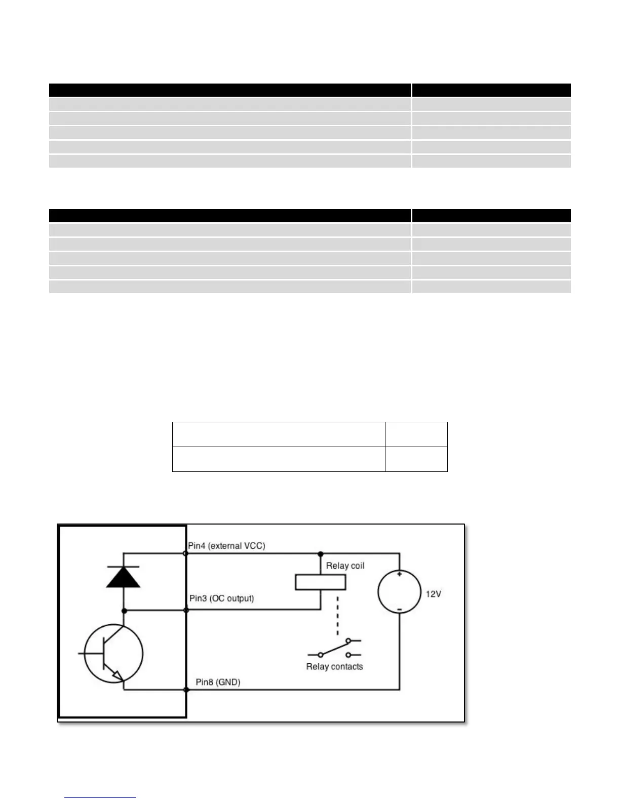
8.17.4.4 Open collector output
This output can be used to drive external relay. In order for the output to work correctly, external voltage that is
connected to a relay also needs to be connected to I/O header pin 4. There is flyback diode located inside the device to
protect it from spikes occurring when inductive load (relay coil) is suddenly switched off, so connection of the external
diode is not necessary. The output is isolated from the rest of the circuitry using optocoupler. In case of the output
failure, the rest of the circuit will remain protected.
Maximum external DC voltage
30V
Maximum output sink current
0.3A
Example of driving a relay:
145

Table of Contents

Other manuals for Teltonika RUT9 Series

Questions and Answers:

Question and Answer IconNeed help?

Do you have a question about the Teltonika RUT9 Series and is the answer not in the manual?

Teltonika RUT9 Series Specifications

General IconGeneral
BrandTeltonika
ModelRUT9 Series
CategoryNetwork Router
LanguageEnglish

Related product manuals