2-4
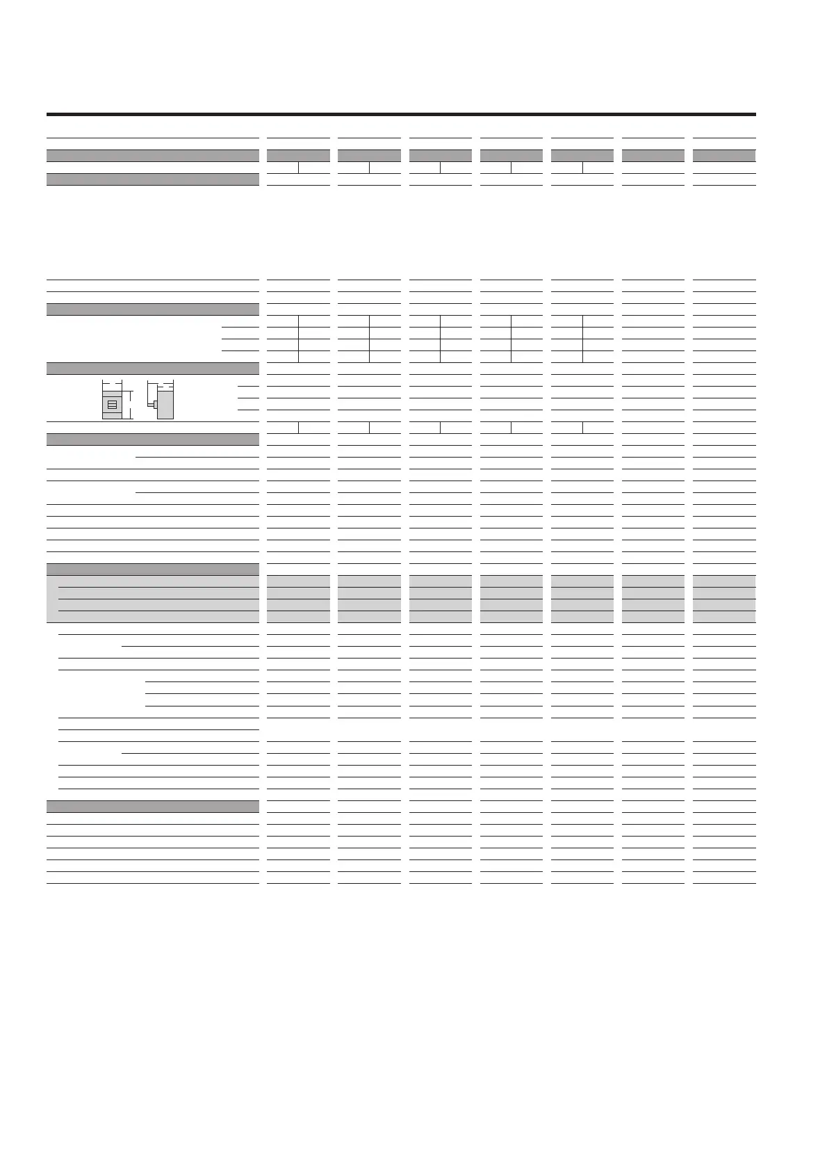
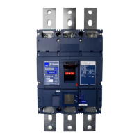
Moulded Case Circuit Breakers for DC350V-600V
Frame size (A)
Type
Number of poles
■Ratings
Rated current, A
Calibrated at 45°C
*2 poles breaker is same outline dimensions as
3 poles breaker.
Rated insulation voltage〔
U
i
〕 V
Rated impulse withstand voltage 〔
U
imp
〕 kV
■Rated breaking capacity, kA
JIS C 8201-2-1 Ann.1 Ann.2 DC 600V
IEC 60947-2 500V
I
cu
/I
cs
④⑤ 350V
250V
■External dimensions, mm
a
b
c
d
Weight (' marked standard type) kg
■Connections and Mountings
Front-connected (FC) Terminal screws
With extension bars
Rear-connected(RC) Flat bar studs
Plug-in (PM)
For switchboards
For distribution boards
Draw-out type (DR)
TemPlug70 (PG)
TemPlug45B (PG4)
DIN rail mount
Clip-in chassis mount
■Accessories (optional) Symbol
Auxiliary switch AX
Alarm switch AL
Shunt trips SH
Undervoltage trips UV
Motor operator MC
External operating
Breaker-mounted HB
handle
Door-mounted (variable depth)
HP
Toggle extension HA
Mechanical interlock Slide type MS
Rear-connected type MB
Link type ML
Wire type MW
Toggle holder HH
Toggle lock HL
Terminal cover For front-connected CF
For rear-connected and plug-in CR
Interpole barrier BA
Terminal block for lead TF
Door flange DF
■Standard specifications
Overcurrent trip mechanism
Colourofcover
Trip button (Colour)
Handle position indication (ON: Red, OFF: Green)
Suitability for isolation
Reverse connection
1600
XS1600ND
2* 3
1600 ①
690
8
― 20/15
― 50/25
― 50/25
50/30 ―
210
370
140
191
24.027.0
―
○
'
―
―
○
―
―
―
―
●
●
●
―
●
●
●
●⑥
―
―
―
―
●
―
―
●③
●
●
Magnetic(adjustable)
①
Grey
Yes (Red)
Yes
Yes
Non
2000
XS2000ND
2* 3
2000 ①
690
8
― 20/15
― 50/25
― 50/25
50/30 ―
320
450
185
245
50.054.0
―
○
'
―
―
○
―
―
―
―
●
●
●
―
●
―
●⑦
●②
―
―
―
―
●
―
―
―
●
●
Magnetic(adjustable)
①
Grey
Yes (Red)
Yes
Non
Non
2500
XS2500ND
2* 3
2500 ①
690
8
― 20/15
― 50/25
― 50/25
50/30 ―
320
450
185
245
55.762.5
―
―
'
―
―
―
―
―
―
―
●
●
●
―
●
―
●⑦
●②
―
―
―
―
●
―
―
―
●
●
Magnetic(adjustable)
①
Grey
Yes (Red)
Yes
Non
Non
3200
XS3200ND
2* 3
3200 ①
690
8
― 20/15
― 50/25
― 50/25
50/30 ―
320
450
185
245
55.762.5
―
―
'
―
―
―
―
―
―
―
●
●
●
―
●
―
●⑦
●②
―
―
―
―
●
―
―
―
●
●
Magnetic(adjustable)
①
Grey
Yes (Red)
Yes
Non
Non
1250
XS1250ND
2* 3
1250 ①
690
8
― 20/15
― 50/25
― 50/25
50/30 ―
210
370
140
191
23.826.0
―
'
○
―
―
―
―
―
―
―
●
●
●
―
●
●
●
●⑥
―
―
―
―
●
―
―
●③
●
●
Magnetic(adjustable)
①
Grey
Yes (Red)
Yes
Yes
Non
Notes:
' : Standard. This configuration used unless otherwise specified. ○ : Optional standard. Specify when ordering. ● : “yes” or “available”. ― : “no” or “not available”.
① : Instantaneous trip oinly.
②
: Supplied as standard.
③
: Line side interpole barriers are supplied as standard. (Front connection only)
④
: Connect 3pole in series when over DC250V.
⑤
: The time constant (L/R) of the circuit should be,
less than 2.0ms nearby rated current
less than 5ms for short circuit ≦ 10KA
less than 10ms for short circuit ≦ 20KA
less than 15ms for short circuit > 20KA
⑥
: One is supplied with every five breakers. Please specify if more are required.
⑦
: Fixed depth. (not adjustable)
InteriorExterior


 To Next Page