6-13
6
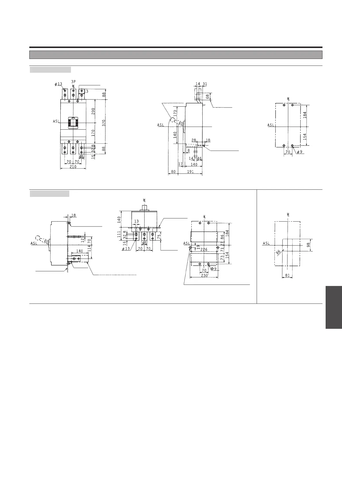
Outline Dimensions
ASL : Arrangement Standard Line
H
L
: Handle Frame Centre Line
C
L
: Handle Centre Line
Outline dimensions (mm)
X
S1250ND 2P, 3P
Front-connected
Rear-connected
Note: 2 poles breaker is same outline dimensions as 3 poles breaker.
Drilling plan (front view)
Conductor
overlap, max
M8
Mounting screw
Toggle extension
(removable)
Mounting hole
Drilling plan (front view) Panel cutout (front view)
Conductor
overlap, max
Mounting plate
M8 Mounting screw
Insulating plate
Panel cutout dimensions shown give an
allowance of 1.5mm around the handle
escutcheon.
ø15 for accessory wiring when necessary
Soft plastic tubing ø50 to be
provided on center pole and
neutral pole of vertical
terminal type for insulation.
Mounting plate
Note: Studs are factory installed in horizontal direction both on the line and load sides.
Please specify when ordering if vertical direction is reqired.
 Loading...