6-17
6
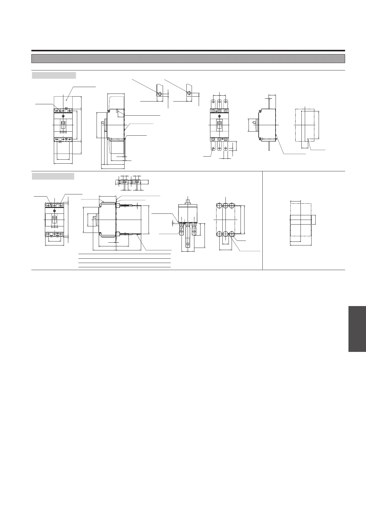
Outline Dimensions
ASL : Arrangement Standard Line
H
L
: Handle Frame Centre Line
C
L
: Handle Centre Line
Outline dimensions (mm) PVE160-SDL 3P
C
L
C
L
L
H
L
H
L
H
Front-connected
Rear-connected
Drilling plan (front view)
M4✕0.7
Tapped hole
M4✕0.7
Mounting screw
Panel cutout (front view)
Detail of
connecting part
Mounting plate (max. t3.2)
Studs are horizontal
direction only
Panel cutout dimensions shown give an allowance
of 1.0mm or more around the handle escutcheon.
✽ Straight bars only.
For line and load side, use with the terminal covers.
With extension bars ✽
(optional)
Drilling plan
(front view)
Preparation of
conductor
Insulating plate
Insulating plate
25
50
CD
E
A
3P
111
114
ø20
37.5
3P
38.5
77
B
CD
A
B
100.4
50.4
114
69.6
102
F
96.6
3P
6.1
25 25
100.4
50.4
6.5(max.)
9(max.)
16.5(max.)
max.t5
14(max.)
max.t5
ø5.5(25-40A)
ø9(63-160A)
ø5.5(25-40A)
ø9(63-160A)
45
C
L
C
L
C
L
C
L
C
L
L
H
L
H
L
H
25
75
50
50
102
6.1
25.6
67.6
96.6
53.6
69.6
3P
10.5
3P
5050 130
111
3P
8.5
5.63
17
114
25 25
ø8.3
45
29.6
4
C
L
L
H
75
3P
5.35.3 130
67.6
22
22
1.6t
Insulating plate
Insulating plate
48
1.6t
M4✕0.7
Tapped hole
Terminal cover
M4✕0.7
Mounting screw
M5✕0.8 screw (25-40A)
M8 screw (63-160A)
Terminal cover
Terminal cover
Mounting hole
Mounting hole
Rated current
(A) A B C D E
25-40 10.56.5
41316
63-160 12.58.5
41316
F
4
5
 Loading...