6-10
ASL : Arrangement Standard Line
H
L
: Handle Frame Centre Line
C
L
: Handle Centre Line
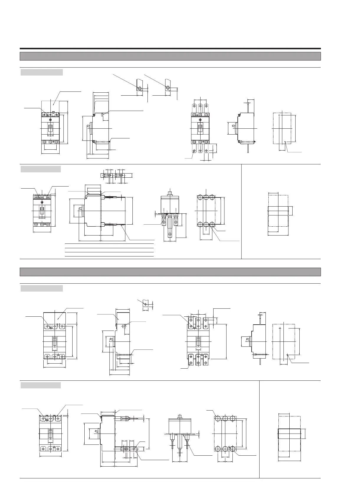
DC Moulded Case Circuit Breakers
Outline dimensions (mm) S160-SD 3P, S160-GD 3P, S160-SDN 3P
Outline dimensions (mm) S250-SD 3P, S250-GD 3P, S250-SDN 3P
C
L
C
L
L
H
L
H
L
H
Front-connected
Rear-connected
Drilling plan (front view)
M4✕0.7
Tapped hole
M4✕0.7
Mounting screw
Panel cutout (front view)
Detail of
connecting part
Mounting plate
(max. t3.2)
Studs are horizontal
direction only
Panel cutout dimensions shown give an allowance
of 1.0mm or more around the handle escutcheon.
✽ Straight bars only.
For line side, use with the terminal cover.
With extension bars ✽
(optional)
Drilling plan
(front view)
Preparation of
conductor
25
50
CD
E
A
3P
111
114
ø20
37.5
3P
38.5
77
B
CD
A
B
102
52
114
68
102
F
95
3P
7.7
25 25
102
52
6.5(max.)
9(max.)
16.5(max.)
max.t5
14(max.)
max.t5
ø5.5(25-40A)
ø9(63-160A)
ø5.5(25-40A)
ø9(63-160A)
45
C
L
C
L
C
L
C
L
C
L
L
H
L
H
L
H
M4✕0.7
Tapped hole
Terminal cover
M4✕0.7
Mounting screw
M5✕0.8 screw (25-40A)
M8 screw (63-160A)
25
75
50
102
7.7
24
66
61
60.3
95
68
52
3P
10.5
3P
50130
111
3P
8.5
5.63
17
114
25 25
ø8.3
45
28
4
C
L
L
H
75
3P
5.3130
66
57
56
22
22
Terminal cover
Terminal cover
Mounting hole
Mounting hole
48
Rated current
(A) A B C D E
25-40 10.56.5
41316
63-160 12.58.5
41316
F
4
5
C
L
C
L
C
L
C
L
C
L
C
L
C
L
C
L
L
H
L
H
L
H
C
L
L
H
L
H
L
H
L
H
7
23
45
3P 3P
3P
3P
ø24
35
13
9
7
102
144
144
20
6
126
ø9
6
35
16
68
60
107
72
3535 35
3P
65.5
65.5
30.5
11.519
165
3535
102
55
165
144
45
126
7
35
24
46
105
70
24 21
ø11
10.5
95
68
60
28
4
22
3P
5.3
165
105
22
22
25(max.)
max.t7
11(max.)
ø9
45
3P
Mounting hole
Terminal cover
Mounting hole
Terminal cover
Terminal cover
Terminal cover
M8 screw
M4✕0.7
Mounting screw
M4✕0.7
Tapped hole
Conductor
overlap, max
Mounting hole
✽ Straight bars only.
For line side, use with the terminal cover.
Drilling plan (front view)
M4✕0.7
Tapped hole
M4✕0.7
Mounting screw
Panel cutout (front view)
Detail of
connecting part
Mounting plate
(max. t3.2)
Stud can be turned
45° or 90°
Panel cutout dimensions shown give an
allowance of 1.0mm around the handle
escutcheon.
Conductor
overlap, max
52.5
53.5
107
48
Preparation of
conductor
With extension bars ✽
(optional)
Drilling plan
(front view)
Front-connected
Rear-connected
 Loading...