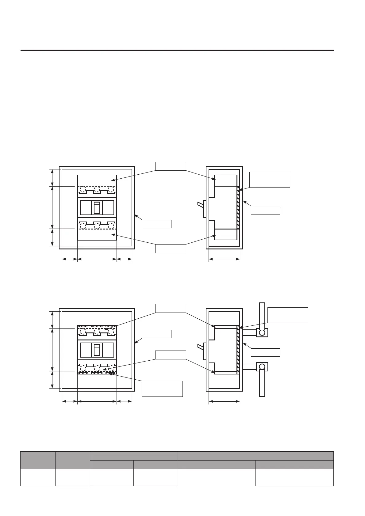
Insulation distance DC750V-1000V
The insulation distances between the breaker and earthed metal parts and insulators shown in the table below must be
maintained to prevent arcing faults occurring due to conductive ionised gas. In addition, any exposed line-side conductors
must be completely covered, right up the breaker casing or to below the height protected by any terminal covers or interpole
barriers. This can done by using an insulation tube or tape, in order to provide positive protection against short circuit or
ground fault due to metal chipping, surge voltage, dust particles or salt. The terminal covers or the interpole barriers supplied
with the breaker as standard must be used. For DC750V-1000V breakers, the front and the rear insulating plates must also
be installed.
B 130 B
A75 70
70
A
B 130 B
A75
A
Terminal cover
Terminal cover
Insulating plate
(supplied as standard)
Mounting plate
Insulating plate
(supplied as standard)
Mounting plate
Mounting plate
Terminal cover
Terminal cover
Insulating plate
(supplied as standard)
Mounting plate
PVE160-SDL 3P
Front-connected
Rear-connected
Type Connection
PVE160-SDL 3P
Front-connected
Rear-connected
25
Minimum insulation distance (mm) Insulating plate
A B
Terminal cover
50
2pcs are supplied for line
and load side as standard.
Insulating plate
1pc of 130mm×75mm for F.C.
or 140mm×75mm for R.C. is
supplied as standard.
4-8
 Loading...