6-14
ASL : Arrangement Standard Line
H
L
: Handle Frame Centre Line
C
L
: Handle Centre Line
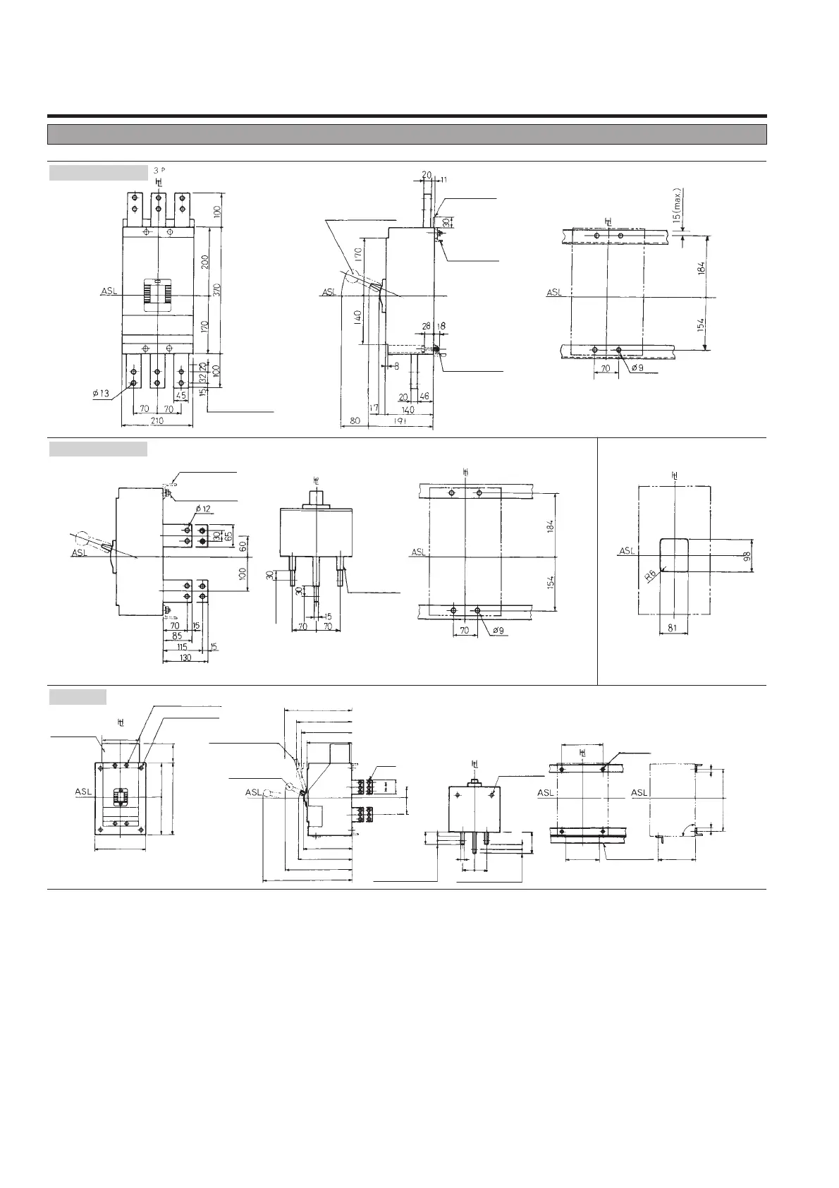
DC Moulded Case Circuit Breakers
Outline dimensions (mm)
X
S1600ND 2P, 3P
Draw-out
Front-connected
Note: 2 poles breaker is same outline dimensions as 3 poles breaker.
Rear-connected
Drilling plan (front view)
Breaker fixing screw
Mounting hole
300 (max.)
220
220
420 105
75
50
2520
25
120
20
70
100
170190
20 20
60
200
ø12
Mounting hole
Mounting angle
526 (draw-out)
396 (connected)
282
316
395 (draw-out)
325 (disconnected)
ø12
ø12
15
70
200 215
225
70
295 (test)
265 (connected)
Draw-out handle
(removable)
Auxiliary
circuit terminals
(Automatic connection)
Conductor overlap, max
Conductor overlap, max
Conductor
overlap, max
Conductor
overlap, max
Mounting angle
()
ON side Center pole
OFF side All poles
Insulation tube
Panel cutout dimensions shown give an
allowance of 1.5mm around the handle
escutcheon.
Panel cutout (front view)
Drilling plan (front view)
Drilling plan (front view)
M8
Mounting screw
M8
Mounting screw
Insulating plate
Mounting angle
Toggle extension
(removable)
※Contact TERASAKI if manual connection is required.
※
Toggle extension
(removable)
90°
3P
 Loading...