6-11
6
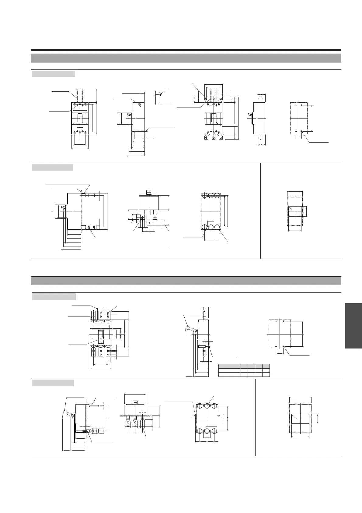
Outline Dimensions
ASL : Arrangement Standard Line
H
L
: Handle Frame Centre Line
C
L
: Handle Centre Line
Outline dimensions (mm) S800-ND 3P
H
L
H
L
H
L
H
L
H
L
ASL
ASL
3P
ASL
3P
3P
ASL
ASL
ASL
103
107
28
13
4
145
70
70
13
70
70
43
43
117
126
10
42
122
103
30.5
80.5
117 126
3P
ø13
ø
48
127.5
R6
ø
13
70
140
210
3P
172
40
13
70
80
273
80
92
55.5
46.5
117
126
141
132
t2
L2
t1
L1
103
107
145
28
13
127.5
4
80.5
51
170
90
25
253220
15
8
8
32
L1 L2 t1
32 34 8
32 35 10
t2
8
10
630
800
Front-connected
Drilling plan (front view) Panel cutout (front view)
Drilling plan (front view)
Conductor
overlap, max
Conductor
overlap, max
Stud can
be turned 90°
M8
Tapped hole
M8
Mounting screw
Interpole barrier
(removable)
Mounting hole
M8
Mounting screw
Panel cutout dimensions shown give an allowance
of 1.0mm around the handle escutcheon.
Note: Studs are factory installed in horizontal direction both on the line and load sides.
Trip button
(red)
ø15 for accessory wiring
when necessary
Rated Current (A)
Toggle extension
(removable)
Toggle extension
(removable)
M8
Tapped hole
Rear-connected
Outline dimensions (mm) S400-ND 3P
C
L
Drilling plan (front view) Panel cutout (front view)
Front-connected
Rear-connected
Panel cutout dimensions shown
give an allowance of 1.0mm
around the handle escutcheon.
Preparation of
conductor
With extension bars
(optional)
Drilling plan (front view)
M10 screw
M6
Tapped hole
Interpole barrier
(removable)
Interpole barrier
(removable)
Mounting hole
M6
Mounting screw
(With handle cap)
On side 36
Off side 35
Conductor
overlap max.
Conductor
overlap max.
M6
Tapped hole
Mounting plate
Stud can be turned 45° or 90°
Note: Studs are factory installed in horizontal direction both on the line and load sides.
L
H
L
H
L
H
90
116
51
85.3 14.7
836
835
45
97
103
107
127.5
145
97
103
1074
127.5
145
4
140
260
102
90
102
90
214
110
228
260
228
8
30
C
L
C
L
C
L
C
L
C
L
C
L
12
(max.)
ø11
ø13
214
228
ø36
30
(max.)
max. t10
3P
L
H
45
90
C
L
C
L
3P
L
H
118
92
R6
3P
30
45 45
103110
70
15
39
15
39
ø13
120
28
14.530
44.5
30
14.5
44.5
ø14
148
44.5
349
260
Trip button
(red)
 Loading...