4-7
4
Mounting and Connection
Insulation distance DC600V or less
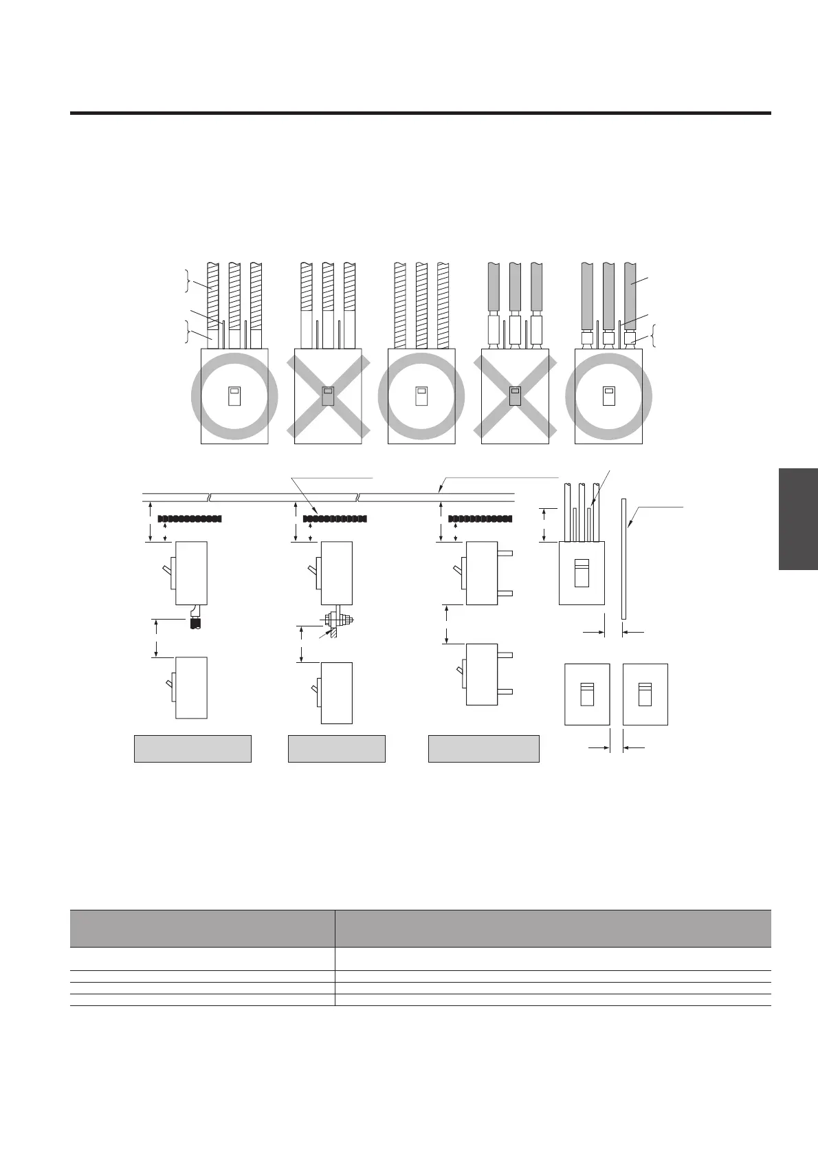
The insulation distances between the breaker and earthed metal parts and insulators shown in the table below must be
maintained to prevent arcing faults occurring due to conductive ionised gas. In addition, any exposed line-side conductors
must be completely covered, right up the breaker casing or to below the height protected by any interpole barriers. This can
done by using an insulation tube or tape, in order to provide positive protection against short circuit or ground fault due to
metal chipping, surge voltage, dust particles or salt. If terminal covers are not being used, the interpole barriers supplied with
the breaker as standard must be used.
A . Distance from lower breaker to exposed live part of upper breaker terminal (front connection) or distance from
lower breaker to end face of upper breaker (rear connection).
B1. Distance from end face of breaker to top plate.
B2. Distance from end face of breaker to insulation plate.
C . Gap between breakers.
D . Distance from side of breaker to side plate (earthed metal).
E . Dimension of insulation over exposed conductors.
Front connection,
terminal screw
Front connection,
extension bar
Rear connection,
Plug-in
B1
A
B2
B1
A
B2
B1
E
D
C
A
B2
Insulation plate
Insulation tube
or tape
Top plate (earthed metal)
Side plate
Interpole
barrier
(Insulation tube or tape
is also acceptable)
Insulating
tube or tape
Interpole barrier
Sheathed wire
Interpole barrier
Line side
(ON side)
Load side
(OFF side)
Exposed
conductor
Compression
terminal
Notes:
①. Required to allow free and uninterrupted flow of arc gases. Ensure additional clearance or insulation distance if required to perform wiring, barrier installation or electrical work or to meet
the need for more insulation distance between bare live parts and grounded metal members in a switchboard or the like.
②. The figures are for lower breakers.
③. When the accessories are fitted it is not possible to set close.
④. For front connected breakers, insulate all exposed conductors of the line side until the breaker end. If interpole barriers are packed, be sure to use the barriers; more over, insulate all
exposed conductors by insulating tape or the like so that the tape overlaps with the barriers.
⑤. Be sure to install the terminal covers (supplied as standard) on the line side of the breakers.
✽. If using extension bars (optional), ensure the insulation distance specified for the application.
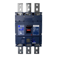
Moulded Case Circuit Breakers
B1 B2
D
E
S400-ND
120 80
〃
80
〃
XS1250ND XS2500ND
150 100
〃
100
〃
A
Note ②
S800-ND S1000-ND
150
XS1600ND XS2000ND
150
Insulation distance, mm (DC 600 V or less) Note①
S160-SD S160-GD S160-SDN
⑤
50 50 50
✽
Possible to set close
Note ③
25
Not less than the length of
the bare live part Note
④
S250-SD S250-GD S250-SDN
⑤
65 65 65
✽
〃
50
〃
C
XS3200ND