Maintenance Manual November 2021
Programmed Maintenance Procedures
82 Scissor Lifts Part No. 1305686GT
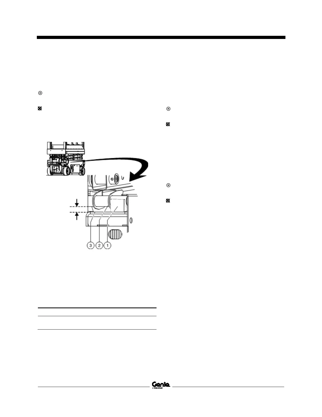
2 Measure the distance between the number
one inner arm cross tube and the chassis
deck at the battery pack side of the non-steer
end of the machine. Refer to illustration 1.
Result: The measurement is 0.90 inch /
22.9 mm or more. Proceed to step 3.
Result: The measurement is less than
0.90 inch / 22.9 mm. Replace both wear pads.
Refer to Repair Procedure in the appropriate
Service and Repair Manual for your machine,
How to Replace the Scissor Arm Wear Pads.
Illustration 1
1 wear pad
2 inner arm cross tube
3 chassis deck
3 Apply a thin layer of dry film lubricant to the
area of the chassis where the scissor arm
wear pads make contact.
Cross tube to chassis specification
0.90 i
22.9 m
GS-2032, GS-2632, GS-3232, GS-2046, GS-2646,
GS-3246:
1 Measure the distance between the number
one outer arm cross tube and the fork lift tube
at the ground controls side of the non-steer
end of the machine. Refer to Illustration 2.
Result: The measurement is 0.88 inch /
22.4 mm or more. Proceed to step 2.
Result: The measurement is less than
0.88 inch / 22.4 mm. Replace both wear pads.
Refer to Repair Procedure in the appropriate
Service and Repair Manual for your machine,
How to Replace the Scissor Arm Wear Pads.
2 Measure the distance between the number
one outer arm cross tube and the fork lift tube
at the battery pack side of the non-steer end
of the machine. Refer to Illustration 2.
Result: The measurement is 0.88 inch /
22.4 mm or more. Proceed to step 3.
Result: The measurement is less than
0.88 inch / 22.4 mm. Replace both wear pads.
Refer to Repair Procedure in the appropriate
Service and Repair Manual for your machine,
How to Replace the Scissor Arm Wear Pads.

 Loading...