Chapter Overview
This chapter provides disassembly and assembly pro-
cedures for the loader and transmission controls.
Personal Safety
Improper or incomplete maintenance/repair of a Compact
Track Loader can be dangerous and may result in ma-chine
damage, injury or death.
Do not attempt to perform any type of repair or mainten-ance
on a Compact Track Loader until you have read and fully
understood the information in this manual. Refer to the
Operation and Maintenance manual for in-structions regard-
ing proper machine operation techniques before operating
any Compact Track Loader.
Prior to performing any type of service work on a Compact
Track Loader, read and understand Chapter 1 (Product
Safety) for personal safety information.
Machine Preparation
Accidental machine starting can cause injury or death to per-
sonnel working on a Compact Track Loader.
As a precaution, disconnect the battery cables from the bat-
tery terminals, tape the battery clamps and remove the key
from the ignition switch prior to per-forming any service work
on a Compact Track Loader.
Place a “Do Not Operate” tag prominently on the machine to
inform personnel that the machine is be-ing worked on.
Loader/Transmission Controls
Disassembly and Assembly
Procedures
Disassembly and assembly procedures are provided
for the following loader/transmission control compo-
nents.
• Drive Control Joystick
• Loader Control Joystick
• Loader Float Magnet
• Loader Valve
Note: Procedures are provided for only those
loader/transmission control components listed above.
However, information for removal and installation of
other loader/transmission control components can be
obtained from the Compact Track Loader Parts List
manual.
Note: Refer to Figure 3-2 for an overview of the auxil-
iary circuit system and Figure 3-3 for an overview of
the drive loop system.
Loader Control Joystick/Drive
Control Joystick Removal and
Installation
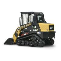
There are two joysticks that control the operation of the
machine: a drive control joystick and a loader control
joystick.
Drive Control Joystick Operation – The left-hand
joystick controls the speed and direction of the ma-
chine. The further the joystick is pushed, the faster the
machine travels. The joystick operates on hy-draulic
charge pressure. When the joystick is moved, oil is
sent to the hydrostatic transmission. The transmission
then delivers oil, in the correct amount, to the drive
motors.
9. Loader/Transmission Controls
Disassembly and Assembly
9-1