Compact Track Loader
12. Undercarriage Disassembly and Assembly
12-11
Note: During disassembly, cap all hoses and fittings to
prevent fluid loss and contamination of the system fluids.
Drive Motor Removal
Figure 12-41
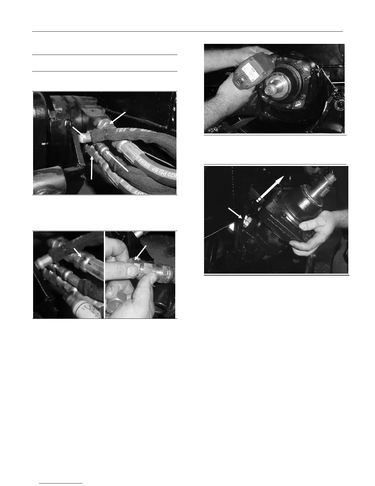
1. Locate four drive motor hoses in back of drive
motor.
Figure 12-42
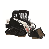
2. Mark the top (T) and bottom (B) large hoses to
ensure proper re-installation. For ease of
removal, remove hoses in this order: angled
small, top large, straight small, bottom large. It
is important to cap fittings and plug drive
hoses to ensure hydraulic systems is free from
debris.
Figure 12-43
3. Remove the four bolts that secure the drive
motor to the drive table using a thin wall socket.
Figure 12-44
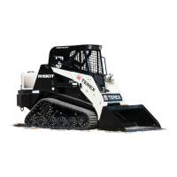
4. Remove drive motor by turning motor with the
hydraulic hose fittings facing upward and
angle the motor out of the table weldment and
pull in upward motion.
Drive Motor Installation
1. Position the drive motor so the hydraulic fittings
enter in the correct location. Install the drive
motor bolts. Clean and inspect the drive motor
shaft.
2. Re-install all hoses and fitting in the same order
instructions direct in removal.
3. Re-install drive sprocket as outlined above.
Angled Small
Straight Small
Top Large
Bottom Large
“T” marking
Plug
Fittings
on top