Compact Track Loader
12. Undercarriage Disassembly and Assembly
12-9
Figure 12-32B
Sprocket Roller Installation
Figure 12-33
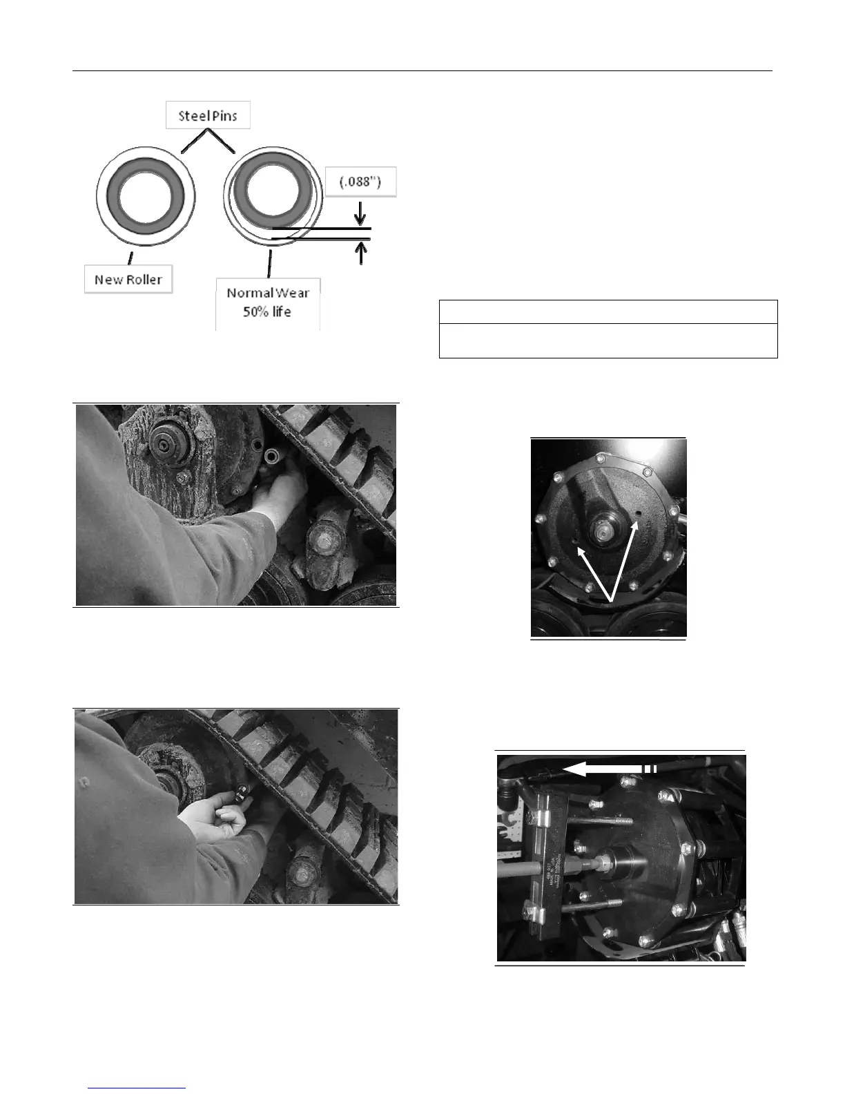
1. With the drive sprocket rotated to the desired
position, position the composite roller and steel
pin in the drive sprocket.
Figure 12-34
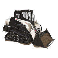
2. Insert the sprocket roller bolt from the rear.
Torque to 62 ft. lbs.
Sprocket Removal and
Installation
The tools required for sprocket removal and
installation are listed in table 12-5 below. Use
manufacturer-recommended tools whenever
possible.
Sprocket Removal
Table 12-5
1. Remove the sprocket bearing plate as described
on page 12-7.
Figure 12-35
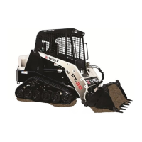
2. Install the puller by positioning the push bolt into
the end of the sprocket shaft and then threading
the puller bolts into the holes in the fac e of the
drive sprocket. (fig. 12-35 & 12-36).
Figure 12-36
Required Tools
Socket Wrench Impact Driver
Sprocket Puller
Puller holes