EasyManuals Logo

Texas Instruments CC2500 User Manual

Texas Instruments CC2500
96 pages
To Next Page IconTo Next Page
To Previous Page IconTo Previous Page
Page #17 background imageLoading...
Page #17 background image
CC2500
S
WRS040
C
Page
17
of
89
6
Circuit Description
BIAS
PA
RBIAS
XOSC_Q1
XOSC_Q2
CSn
SI
SO (GDO1)
XOSC
SCLK
LNA
0
90
FREQ
SYNTH
ADC
ADC
DEMODULATOR
FEC / INTERLEAVER
PACKET HANDLER
RXFIFO
MODULATOR
TXFIFO
DIGITAL INTERFACE TO MCU
RADIO CONTROL
RF_P
RF_N
GDO2
GDO0 (ATEST)
RC OSC
Figure
2
:
CC2500
S
implified
Block D
iagram
A simp
lified block diagram of
CC2500
is shown
in
Figure
2
.
CC2500
features a low
-
IF receiver. The
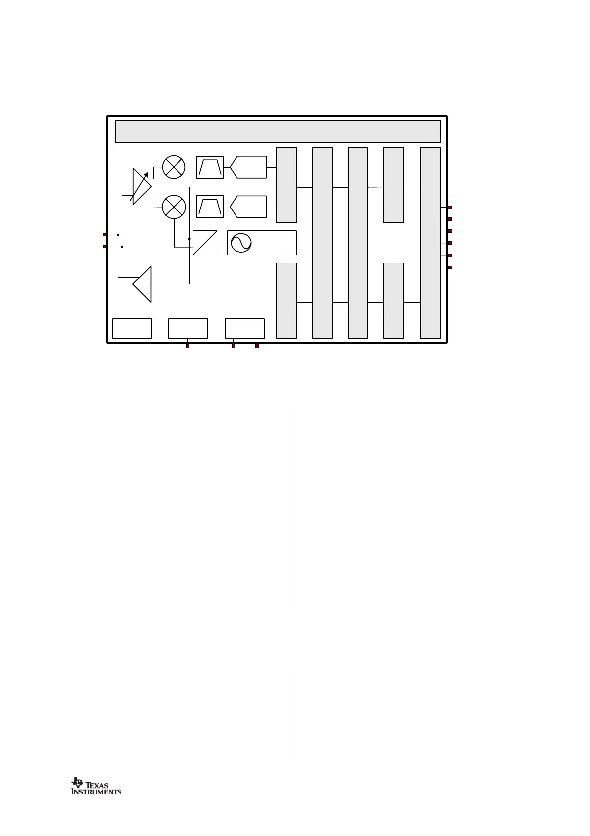
received RF signal is amplified by the low
-
noise amplifier (LNA) and down
-
converted in
quadrature (I and Q) to the interm
ediate
frequency (IF). At IF, the I/Q signals are
digitised by the ADCs. Automatic gain control
(AGC), fine channel filtering, demodulation
bit/packet synchronization
are
performed
digitally.
The transmitter part of
CC2500
is based on
direct synthesis of
the RF frequency.
The frequency synthesizer includes a
completely on
-
chip LC VCO and a 90 degrees
phase shifter for generating the I and Q LO
signals to the down
-
conversion mixers in
receive mode.
A crystal is to be connected to
XOSC_Q1
and
XOSC_Q2
. The
crystal oscillator generates the
reference frequency for the synthesizer, as
well as clocks for the ADC and the digital part.
A 4
-
wire SPI serial interface is used for
configuration and data buffer access.
The digital baseband includes support for
channel
configuration, packet handling
,
and
data buffering.
7
Application Circuit
Only a few external components are required
for using the
CC2500
. The recommended
application circuit is shown in
Figure
3
. The
external com
ponents are described in
Table
14
, and typical values are given in
Table
15
.
Bias
R
esistor
The bias resistor R171 is used to set an
accurate bias current.
Balun and RF
M
atc
hing
The components between the
RF_N
/
RF_P
pins
and the point where the two signals are joined
together (
C122, C132, L121
, and L131)
form a

Table of Contents

Questions and Answers:

Question and Answer IconNeed help?

Do you have a question about the Texas Instruments CC2500 and is the answer not in the manual?

Texas Instruments CC2500 Specifications

General IconGeneral
BrandTexas Instruments
ModelCC2500
CategoryTransceiver
LanguageEnglish

Related product manuals