Crystal Drift Compensation
has a very fine frequency
used to compensate for frequency offset and
The frequency offset between an ‘external’
transmitter and the receiver is measured in the
and can be read back from the
status register as described in
. The measured frequency offset
can be used to calibrate the frequency using
the ‘external’ transmitter as the reference. That
is, the received signal of the device will match
the receiver’s channel filter better. In the same
centre frequency of the transmitted
signal will match the ‘external’ transmitter’s
Spectrum Efficient Modulation
also has the possibility to use
shaping feature improves adjacent
frequency shifting, the spectrum is inherently
broad. By making the frequency shift ‘softer’,
the spectrum can be made significantly
narrower. Thus, higher data rates can be
A differential antenna will eliminate the need
for a balun, and the DC biasing can be
achieved in the antenna topology, see
The CC25XX Folded Dipole reference
contains schematics and layout files
for a CC2500EM with a folded dipole PCB
antenna. Please see DN004
49 type SMD crystal is used in the
crystal package strongly influences the price.
In a size constrained PCB design a smaller,
but more expensive, crystal may be used.
lications, the SLEEP state
with the crystal oscillator core switched off
It is possible to leave the crystal oscillator core
running in the SLEEP state if start
The WOR functionality shoul
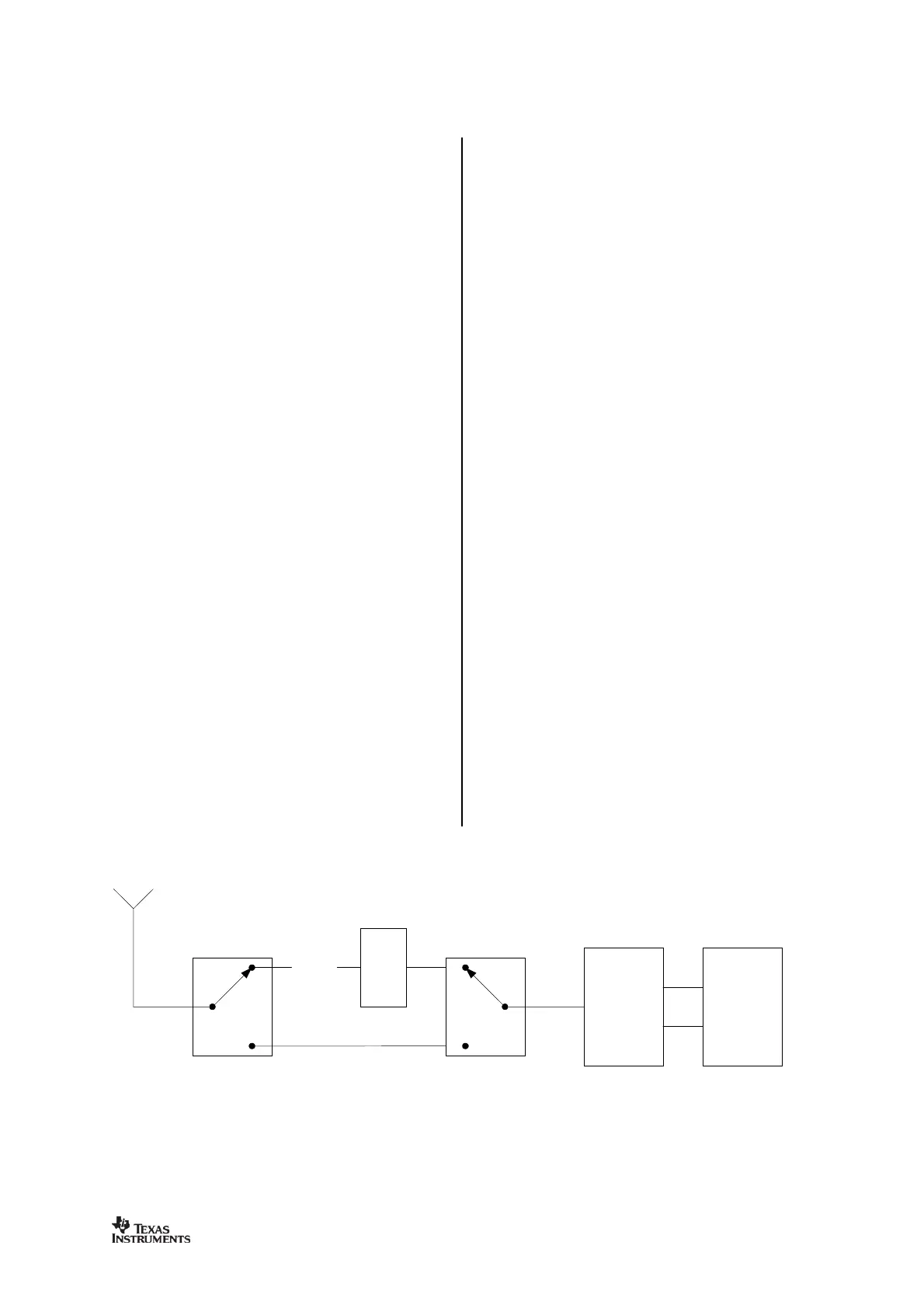
In some applications it may be necessary to
extend the link range. Adding an external
power amplifier is the most effective way of
The power amplifier should be inserted
antenna and the balun, and two
T/R switches are needed to disconnect the PA