EasyManuals Logo

Texas Instruments CC2500 User Manual

Texas Instruments CC2500
96 pages
To Next Page IconTo Next Page
To Previous Page IconTo Previous Page
Page #22 background imageLoading...
Page #22 background image
CC2500
S
WRS040
C
Page
22
of
89
Figure
7
: Configurati
on
R
egister
W
rite and
R
ead
O
perations
Parameter
Description
Min
Max
Units
SCLK
frequency
100 ns delay inserted between address byte and data byte (single access), or between
address and data, and between each data byte (burst access).
-
10
MHz
SC
LK
frequency, single access
No delay between address and data byte
9
MHz
f
SCLK
SCLK
frequency, burst access
No delay between address and data byte, or between data bytes
6.5
MHz
t
sp,pd
CSn
low to positive edge on
SCLK
, in power
-
down mode
150
µs
t
sp
CSn
low to positive edge on
SCLK
, in active mode
20
-
ns
t
ch
Clock high
50
-
ns
t
cl
Clock low
50
-
ns
t
rise
Clock rise time
-
5
ns
t
fall
Clock
fall
time
-
5
ns
Single access
55
-
ns
t
sd
Setup data
(negative
SCLK
edge)
to
positive edge on
SCLK
(t
sd
applies between address and d
ata bytes, and
between data bytes)
Burst access
76
-
ns
t
hd
Hold data after positive edge on
SCLK
20
-
ns
t
ns
Negative edge on
SCLK
to
CSn
high
20
-
ns
Table
16
: SPI
Interface T
iming
R
equir
ements
Note:
The minimum t
sp,pd
figure in
Table
16
can be used in cases where the user does not read the
CHIP_RDYn
signal.
CSn
low to positive edge on
SCLK
when the chip is
woken
from
power
-
down
depends on the start
-
up time of the crystal being used.
The 150 us in
Table
16
is the crystal oscillator
start
-
up time
measured on CC2500EM reference design
(
[4]
)
using crystal AT
-
41CD2 from NDK.
10.1
Chip Status Byte
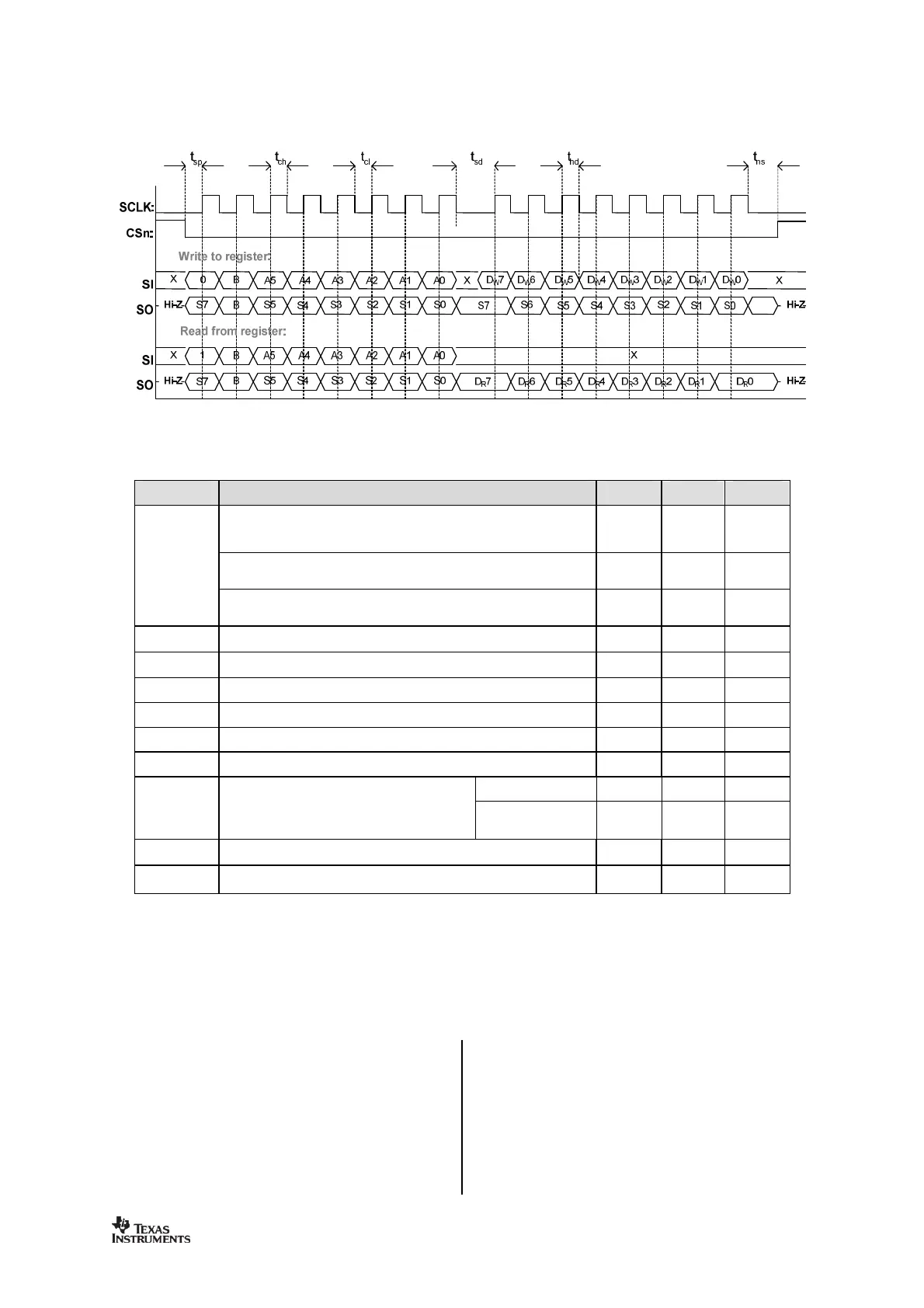
When the header byte, data byte or
,
command
strobe is sent on the SPI interface, the chip
status byte is sent by the
CC2500
on the
SO
pin. The status byte contains key status
signals, useful for th
e MCU. The first bit, s7, is
the
CHIP_RDYn
signal; this signal must go low
before the first positive edge of
SCLK
. The
CHIP_RDYn
signal indicates that the crystal is
running.
Bits 6, 5
,
and 4 comp
rise the
STATE
value.
This value reflects the state of the chip. The
XOSC and power to the digital core is on in
the IDLE state, but all other modules are in
power down. The frequency and channel

Table of Contents

Questions and Answers:

Question and Answer IconNeed help?

Do you have a question about the Texas Instruments CC2500 and is the answer not in the manual?

Texas Instruments CC2500 Specifications

General IconGeneral
BrandTexas Instruments
ModelCC2500
CategoryTransceiver
LanguageEnglish

Related product manuals