Receiver Channel Filter Bandwidth
In order to meet different channel width
requirements, the receiver channel filter is
control the receiver channel filter bandwidth,
which scales with the crystal oscillator
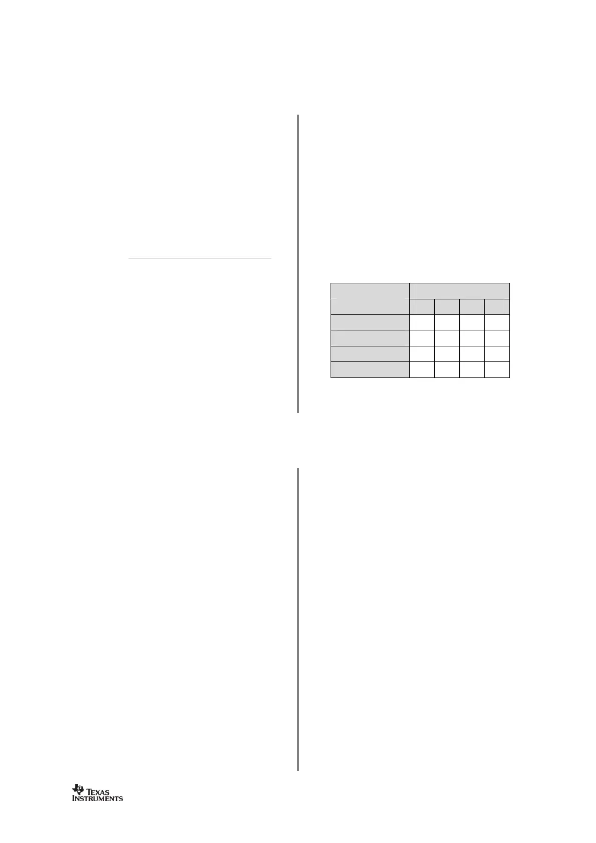
frequency. The following formula gives the
relation between the register settings and the
channel filter bandwidth:
bandwidth should be selected so that the
signal bandwidth occupies at most 80% of the
channel filter bandwidth. The channel centre
tolerance due to crystal accuracy should also
be subtracted from the signal bandwidth. The
With the channel filter bandwidth set to 600
kHz, the signal should stay within 80% of 600
kHz, which is 480 kHz. Assuming 2.44 GHz
frequency and ±20 ppm frequency uncertainty
for both the transmitting device and the
uncertainty is ±40 ppm of 2.44 GHz, which is
±98 kHz. If the whole transmitted signal
bandwidth is to be received within 480 kHz,
the transmitted signal bandwidth should be
Demodulator, Symbol Synchronizer and Data Decision
contains an advanced and highly
configurable demodulator. Channel filtering
and frequency offset compensation is
performed digitally. To generate the RSSI level
for more information) the
signal level in the channel is estimated. Data
filtering is also included for enhanced
Frequency Offset Compensation
modulation, the demodulator will
for the offset between the transmitter and
receiver frequency, within certain limits, by
estimating the centre of the received data.
This value is available in the
register. Writing the value from
synthesizer is automatically adjusted
according to the estimated frequency offset.
The tracking range of the algorithm is
selectable as fractions of the chan
the offset compensator will freeze until
asserts. This may be useful when the
io is in RX for long periods with no traffic,
since the algorithm may drift to the boundaries
when trying to track noise.
The tracking loop has two gain factors, which
affects the settling time and noise sensitivity of
gain before the sync word is detected, and
the sync word has been found.
Note that frequency offset compensation is not
supported for OOK modulation.
The bit synchronization algorithm extracts the
clock from the incoming symbols. The
algorithm requires that the expected data rate
is programmed as described in Section
synchronization is performed
continuously to adjust for error in the incoming