EasyManuals Logo

Texas Instruments CC2500 User Manual

Texas Instruments CC2500
96 pages
To Next Page IconTo Next Page
To Previous Page IconTo Previous Page
Page #44 background imageLoading...
Page #44 background image
CC2500
S
WRS040
C
Page
44
of
89
1.
Read
RXBYTES.NUM_RXBYTES
repeatedly at a rate guaranteed to be at
least twice that of which RF bytes are
received until the same value is returned
twice; store value in
n
.
2.
If
n
<
# of b
ytes remaining in packet
, read
n
-
1 bytes from the RX FIFO.
3.
Repeat
steps 1 and
2 until
n
= # of bytes
remaining in
the
packet.
4.
Read the remaining bytes from the RX
FIFO.
The 4
-
bit
FIFOTHR.FIFO_THR
setting is used
to program thre
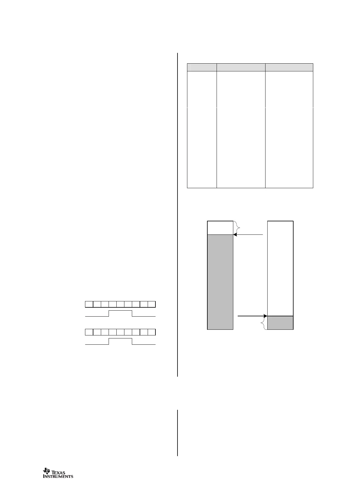
shold points in the FIFOs.
Table
29
lists the 16
FIFO_THR
settings and
the corresponding thresholds for the RX and
TX FIFOs. The threshold value is coded in
opposite directions for the R
X FIFO and TX
FIFO. This gives equal margin to the overflow
and underflow conditions when the threshold
is reached.
A
signal
will assert when the number of bytes
in the FIFO is equal to or higher than the
programmed threshold. The
signal
can be
viewed
on
the
GDO
pins (see Section
28
on
page
51
).
Figure
20
shows the number of bytes in both
the RX FIFO and TX FIFO when the threshold
flag toggles,
in the case of
FIFO_THR
=13
.
Figure
19
shows the
signal
as the respective
FIFO is filled above the threshold, and then
drained below.
53
54
55
56
53
54
55
56
57
6
7
8
9
6
7
8
9
10
NUM_RXBYTES
GDO
NUM_TXBYTES
GDO
Figure
19
:
FIFO_THR
=13 vs. Number of
B
ytes in FIFO (
GDOx_CFG
=0x00 in R
X
and
GDOx_CFG
=0x02 in TX
)
FIFO_THR
Bytes in TX FIFO
Bytes in RX FIFO
0 (0000)
61
4
1 (0001)
57
8
2 (0010)
53
12
3 (0011)
49
16
4 (0100)
45
20
5 (0101)
41
24
6 (0110)
37
28
7 (0
111)
33
32
8 (1000)
29
36
9 (1001)
25
40
10 (1010)
21
44
11 (1011)
17
48
12 (1100)
13
52
13 (1101)
9
56
14 (1110)
5
60
15 (1111)
1
64
Table
29
:
FIFO_THR
S
etti
ngs and the
Corresponding FIFO T
hresholds
56 bytes
8 bytes
Overflow
margin
Underflow
margin
FIF
O_THR=13
FIFO_THR=
13
RXFIFO
TXFIFO
Figure
20
: Example of FIFOs at T
hreshold
21
Frequency Programming
The frequency programming in
CC2500
is
designed to minimize the programming
needed in a channel
-
oriented system.
To set up a system with channel numbers, the
de
sired channel spacing is programmed with
the
MDMCFG0.CHANSPC_M
and
MDMCFG1.CHANSPC_E
registers. The channel
spacing registers are mantissa and exponent
respectively.
The base or start frequency is s
et by the 24 bit
frequency word located in the
FREQ2
,
FREQ1
and
FREQ0
registers. This word will typically

Table of Contents

Questions and Answers:

Question and Answer IconNeed help?

Do you have a question about the Texas Instruments CC2500 and is the answer not in the manual?

Texas Instruments CC2500 Specifications

General IconGeneral
BrandTexas Instruments
ModelCC2500
CategoryTransceiver
LanguageEnglish

Related product manuals