EN - 10
4 Product description EX-TRAFIRE
®
125HD
4 Product description
4.1 Assembly and use
The control elements are located on the control panel. The connections are
on the front and rear of the EX-TRAFIRE
®
125HD.
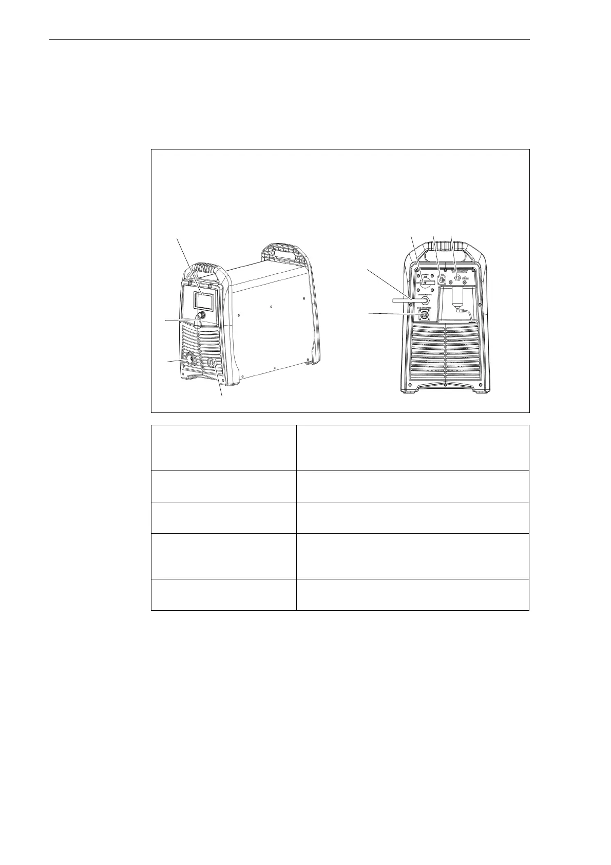
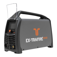
Fig. 2 Control elements and connections
A Display
B <POWER> switch
C Optional BUS interface
D G1/4" gas connection, plug
E Optional CNC interface
F Power cable
G Work lead connection
H Torch connection system (TCS)
I Multi-function button
Digital display (A) Displays the status of the
EX-TRAFIRE
®
125HD. A fault code is
displayed if an error occurs.
<POWER> switch (B) Used to switch the EX-TRAFIRE
®
125HD on
and off.
BUS interface (C) For connecting the optional CAN BUS or
RS485/422 BUS.
CNC interface
connection (E)
This optional interface is used to connect the
EX-TRAFIRE
®
125HD to an optional CNC
cutting table or robot.
Multi-function button (I) For toggling between two menus and
setting the cutting parameters.