EN - 18
6 Setting up the power supply EX-TRAFIRE
®
125HD
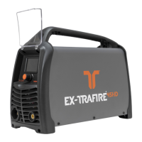
6.6.1 Setting the DIP switches
The DIP switches are preset to 50:1.
1 The housing must be opened only by a qualified electrician.
2 The DIP switches must be set only by a qualified electrician.
Fig. 4 DIP switch settings on page EN-18
3 The housing must be closed only by a qualified electrician.
4 Have a safety inspection performed in accordance with DIN IEC 60974
Part 4: “Periodic inspection and testing” by Thermacut
®
or another
authorized specialist.
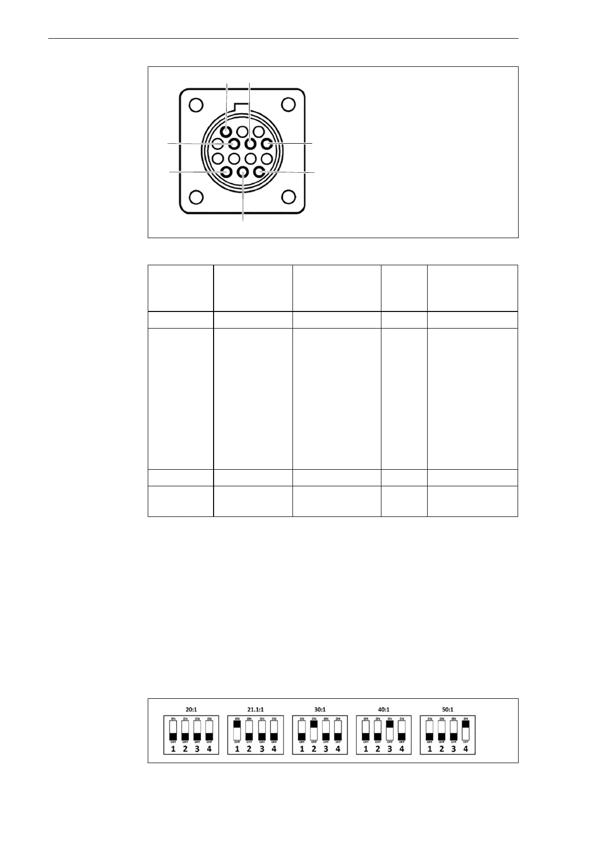
Fig. 3 Pin assignment for CNC interface
Table 9 Pin assignment for CNC interface
Signal START
Start plasma
cutting
Arc
Start feeding
PE Voltage divider
Type Input Output PE Output
Notice Open by
default.
Requires
potential-free
contact to
close.
Open by
default.
Potential-free
with max.
capacity of:
120 V AC/1 A
Reduced arc
signal:
20:1
21.1:1
30:1
40:1
50:1
(supplies max.
10 V)
PIN 3, 4 12, 14 13 6 (+), 5 (−)
Internal
cable color
Yellow, yellow White, white Green/
yellow
6 (red), 5 (white)
Fig. 4 DIP switch settings