POWERMASTER 500, 500P, 350, 350P
March 17, 2006
6-5
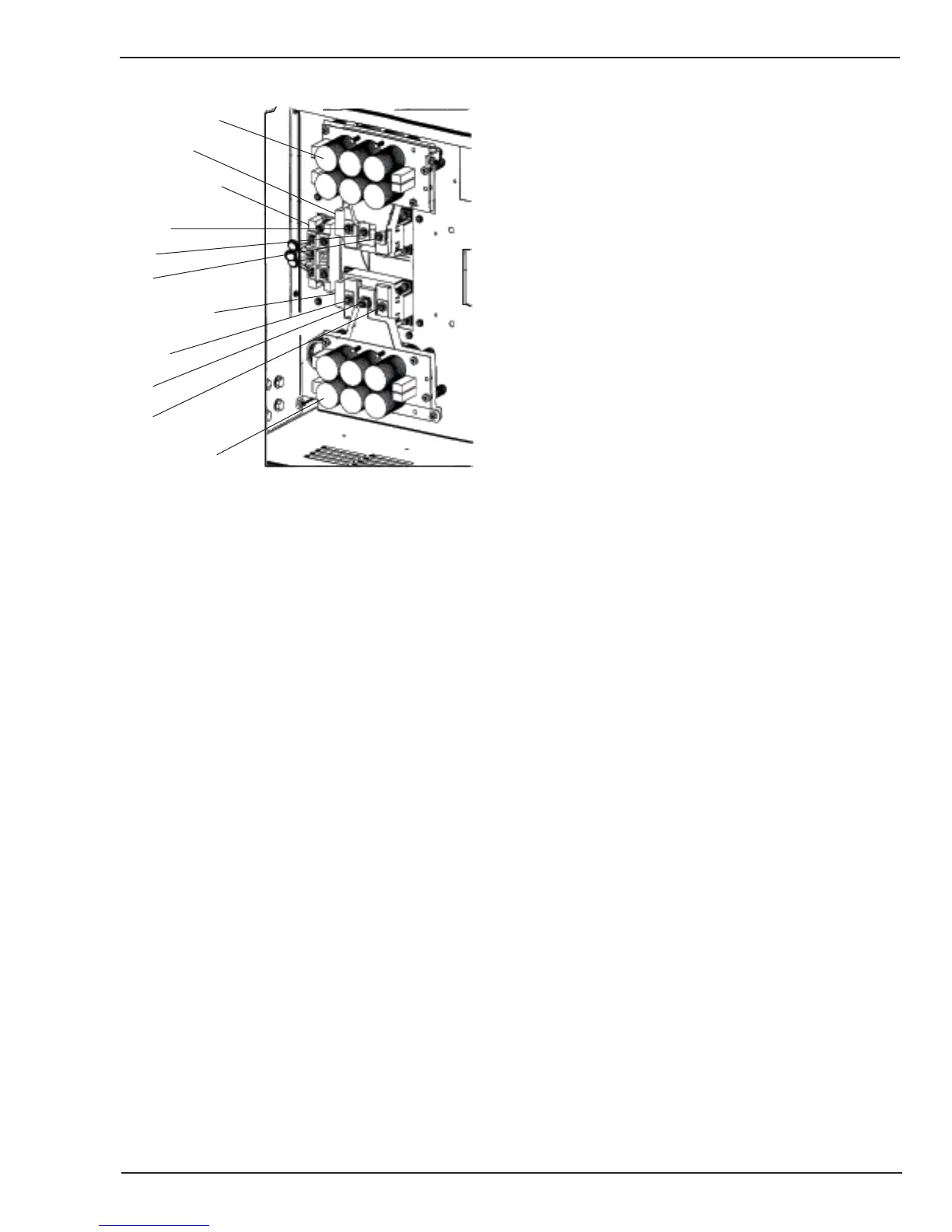
Capacitor BD
Capacitor BD
Input Rectifier
Top IGBT
Bottom IGBT
C2E1
C2E1
E2
C1
C1
E2
Art # A-04091
Figure 6-1: Input Rectifier IGBT Modules
7. How to check the IGBT modules.
A. Refer to Figure 5-1 and/or Appendix 3
Connection Diagram.
B. Using diode checker on digital VOM make the
following checks: (all should read in the range of
0.3 to 0.6 volts).
1) Top IGBT: Positive meter lead on terminal C2E1,
negative meter lead on terminal C1.
2) Top IGBT: Positive meter lead on terminal E2,
negative meter lead on terminal C2E1.
3) Bottom IGBT: Positive meter lead on terminal
C2E1, negative meter lead on terminal C1.
4) Bottom IGBT: Positive meter lead on terminal
E2, negative meter lead on terminal C2E1.
8. How to check the output diodes.
A. Disconnect the weld cables from output terminals.
B. With diode checker setting on VOM, measure across
output terminals with positive meter lead on negative
output terminal. Diode checker should indicate 0.2 to
0.6 volts. If diode checker indicates short, then one
or more of the output diodes is shorted.
9. How to check output open circuit voltage.
A. Disconnect the weld cables from output terminals.
B. Place front panel mode switch in SMAW.
C. Set to LOCAL mode and turn OUTPUT CONTACTOR
switch ON.
D. Measure output terminal voltage, should read
approximately 55 to 70 VDC.
10.Erratic arc
A. Check for loose or incorrect polarity connection to
electrode and work.
B. Check for good gas flow and correct mixture.
C. Is wire feeding smoothly? Check feed rolls, liner,
tip, nozzle, etc.
D. Check welding wire for excess lubrication or
improper cast.
E. Is electronic inductance set correctly, see Operation
chapter of manual.
F. Check voltage and wire speed settings.
G. Torch to work distance too great.
H. Possible defective main control board.
 Loading...