POWERMASTER 500, 500P, 350, 350P
March 17, 2006
6-13
6.07 Power Circuit Tests
Danger:
HIGH VOLTAGE is present internally even with
the control power switch in the OFF position.
Before inspecting, cleaning, or servicing,
disconnect and lock out the input power to the
power source.
The following test must be performed with power
disconnected from the machine. These tests require a
digital multi-meter with a diode checker.
Note;
Normally a good diode will check in the range
of 0.2 to 0.9 Volts in the forward direction
depending on the particular diode.
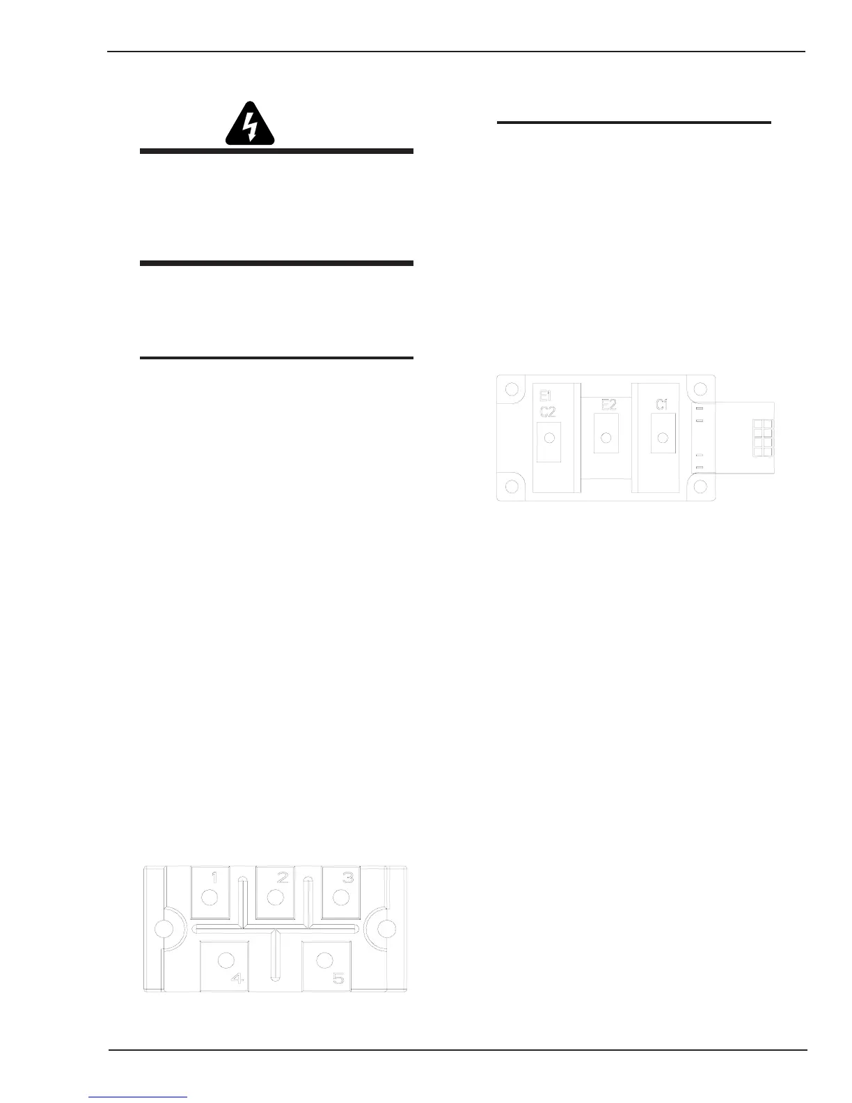
Input Rectifier Test
(see Figure 6-3 and connection diagram)
Terminal 4 (+) to terminal 1 (-) : Open
Terminal 4 (+) to terminal 2 (-) : Open
Terminal 4 (+) to terminal 3 (-) : Open
Terminal 4 (-) to terminal 1 (+) : 0.2 - 0.9
Terminal 4 (-) to terminal 2 (+) : 0.2 - 0.9
Terminal 4 (-) to terminal 3 (+) : 0.2 - 0.9
Terminal 5 (+) to terminal 1 (-) : 0.2 - 0.9
Terminal 5 (+) to terminal 2 (-) : 0.2 - 0.9
Terminal 5 (+) to terminal 3 (-) : 0.2 - 0.9
Terminal 5 (-) to terminal 1 (+) : Open
Terminal 5 (-) to terminal 2 (+) : Open
Terminal 5 (-) to terminal 3 (+) : Open
IGBT Test: (See Figure 6-4 and connection
diagram).
Note:
Because of the capacitor boards connected
across the IGBTs they may initially show a short
circuit when using the diode checker, until the
capacitors charge up.
Check both IGBTs as follows:
E2 (+) to C2E1 (-): 0.2 - 0.9
E2 (-) to C2E1 (+): Open (See Note above)
C2E1 (+) to C1 (-): 0.2 - 0.9
C2E1 (-) to C1 (+): Open (See Note Above)
Art # A-07547
Figure 6-3 IGBT Module
Output Diode test:
Check the output diodes at the output weld terminals as
follows:
Positive terminal (+) to Negative terminal (-): Open
Positive terminal (-) to Negative terminal (+): 0.2 - 0.9
Art # A-07546
Figure 6-2 Input Rectifier




 To Next Page