POWERMASTER 500, 500P, 350, 350P
March 17, 2006
7-1
SECTION 7:
REPAIR PROCEDURES
7.01 Output Diode Replacement:
The following procedure should be used for replacing a
failed output diode module.
The following procedure should be used for replacing a
failed output diode module.
Step 1: Remove the two nuts securing the transformer
bus bars to the diode bus bars.
Step 2: Loosen the bolts on the other end of the two trans-
former bus bars. These bolts do not need to be removed.
Pivot the two transformer bus bars to the side out of the
way.
Step 3: Remove the six bolts holding the diode bus bars
to the diodes. Let the bus bars hang free on the snubber
wires. It is not necessary to remove the wires.
Step 4: Identify the failed diode module/s.
Step 5: Remove the three mounting screws holding the
diode to the heatsink.
Step 6: Clean the heatsink area where the diode mounts.
Step 7. Apply a thin layer of thermal compound to the
back of the diode.
Step 8. Mount diode on heatsink and hand tighten mount-
ing screws. DO NOT TORQUE YET.
Step 9. Attach bus bars to diodes and hand tighten.
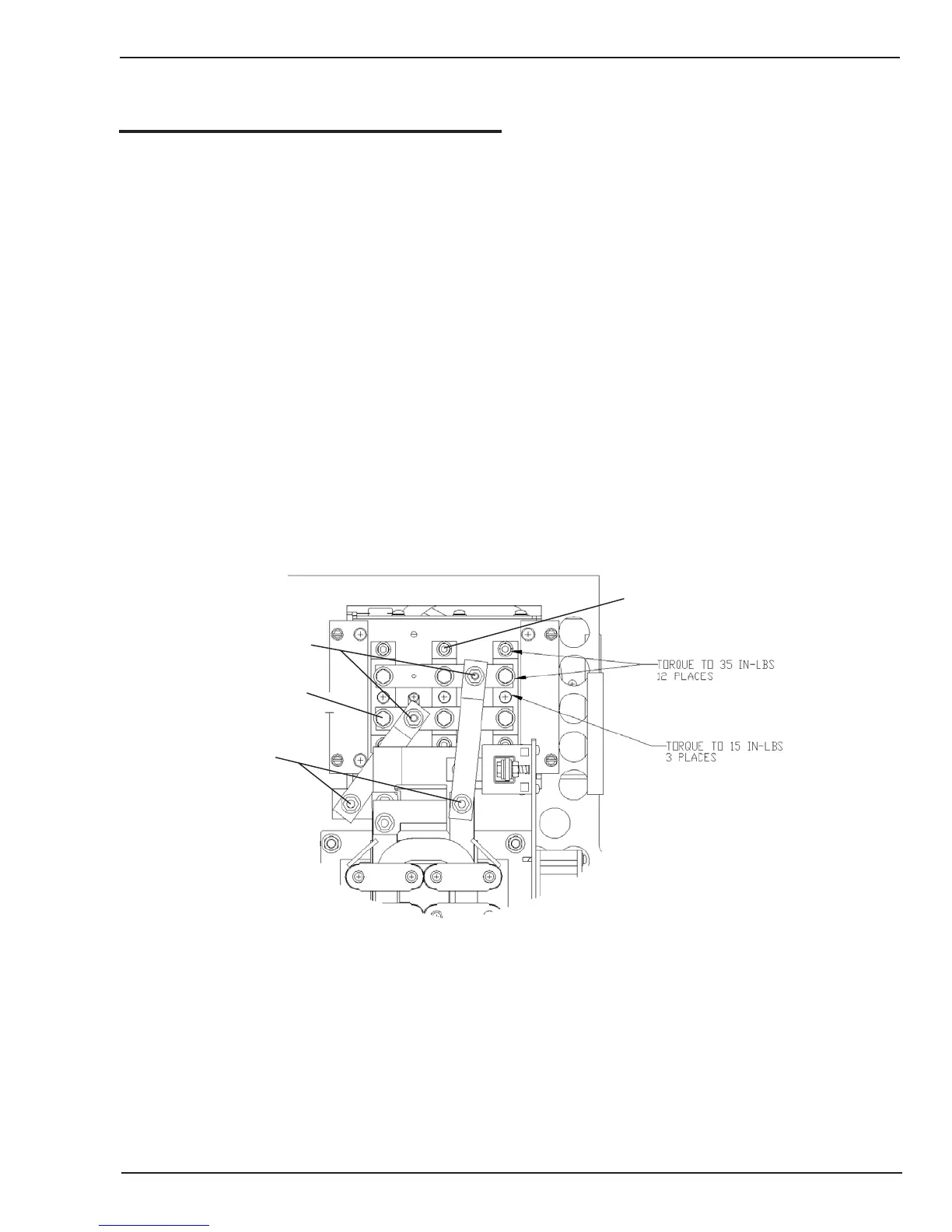
Step 10. Torque the diode mounting screws. (See Figure
7-1). Torque the center mounting screw first, and then
the two outer screws.
Step 11. Torque the six screws holding the bus bars to
the diodes (See Figure 7-1).
Step 12. Reconnect the transformer bus bars.
Step 1
Step 3
Step 2
Step 5
See steps 10 & 1 1
See step 10
Art# A-07542
Figure 7-1: Output Diode Assembly