SERVICE TROUBLESHOOTING 4-6 Manual 0-2725
A-01391
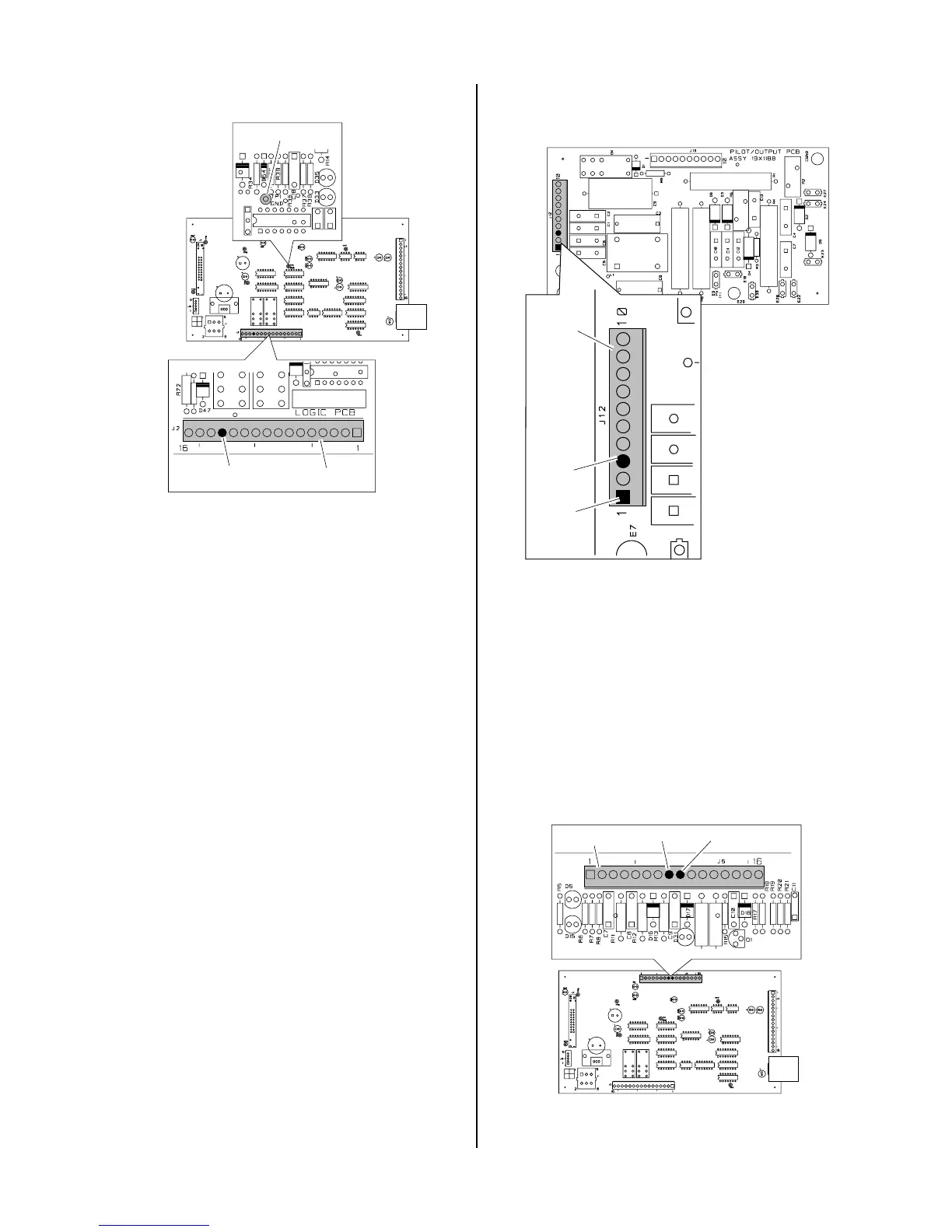
Logic PC
Board
Pin 13
J2
TP1 (GND)
G. Arc in torch without pressing torch switch; AC
indicator ON; Gas flows; GAS and DC indicators
ON
1. Faulty torch switch
a. Refer to appropriate Torch Instruction Manual
and check continuity.
2. Faulty torch leads
a. Refer to appropriate Torch Instruction Manual
and check continuity.
3. Faulty Pilot Output PC Board
Disconnect the Torch Control Cable from the J22
connector.
Remove power from the power supply. Discon-
nect J12 and J13 from the Pilot PC Board.
Check for an open between J12 pin 1 to J12 pin 3
on the Pilot Output PC Board.
a. Replace Pilot Output PC Board if continuity is
present.
A-01399
Pin 3
J12
Pin 1
Pilot Output PC Board
Top
4. Faulty Logic PC Board
Check for 12 vdc from Logic PC Board J5 pin 8 to
J5 pin 9 (ground).
• If voltage is 12 vdc, then check D5 indicator on
the Logic PC Board. Replace Logic PC Board
if D5 is ON.
• If voltage is zero vdc, then replace Logic PC
Board.
A-01392
Logic PC Board
J5
Pin 8
Pin 9

 Loading...


