APPENDIX A-8 Manual 0-2725
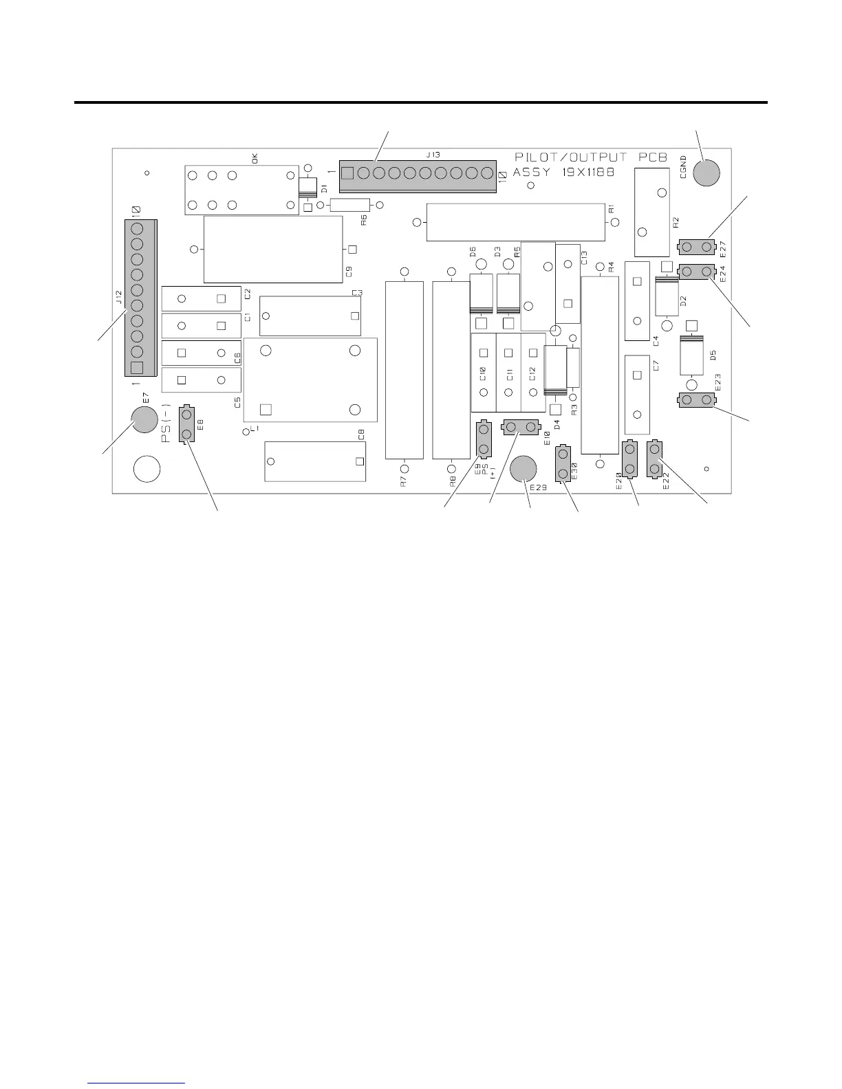
APPENDIX 6: PILOT OUTPUT PC BOARD LAYOUT
Pilot Output PC Board Signals
J12-1 Torch Switch Filter in from J22-3 Torch Control
J12-2 Not Used
J12-3 Torch Switch Filter Return from J22-4 Torch Control
J12-4 Not Used
J12-5 Pilot Return Shield to J22-1 Torch Control
J12-6 Torch Switch Shield to J22-2 Torch Control
J12-7 Not Used
J12-8 OK to Move TO J22-12 Torch Control OK to Move
J12-9 Not Used
J12-10 OK to Move RTN TO J22-14 Torch Control OK to Move RTN
J13-1 Torch Switch Filter out to J5-8 Logic Board Torch Sw
J13-2 Torch Switch Filter gnd out to J5-9 Logic Board Torch Sw gnd
J13-3 OK to Move Relay Coil to Logic PCB J5-10 OK to Move
J13-4 OK to Move Relay Coil to Logic PCB J5-11 +25V
J13-5 PS(+) to Logic Board J5-12 Output Sense Gnd
J13-6 Not Used
J13-7 Tip Voltage Sense to Logic Board J5-14 Drag Sense
J13-8 Not Used
J13-9 PS(-) Sense to Logic Board J5-16 PS(-) Sense (DC and Off the Plate)
J13-10 Not Used
J13
E20
E10
E22
J12
E7
E8
E9
E23
E24
E27
CGND
A-01389
E30
E29
Top

 Loading...


