APPENDIX A-4 Manual 0-2725
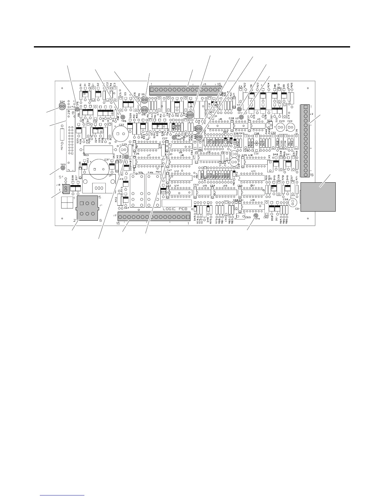
APPENDIX 4: LOGIC PC BOARD LAYOUT
Logic PC Board Signals
J1-1 36 VAC from Auxiliary Transformer
J1-2 115 VAC from Auxiliary Transformer
J1-3 Center Tap from Auxiliary Transformer
J1-4 Not Used
J1-5 36 VAC from Auxiliary Transformer
J1-6 115 VAC Return from Auxiliary Transformer
J2-1 115 VAC Return to Contactor
J2-2 115 VAC Return to Fan #1
J2-3 115 VAC Return to Fan #2
J2-4 115 VAC Return to Solenoid
J2-5 Not Used
J2-6 Not Used
J2-7 115 VAC to Contactor
J2-8 115 VAC Return to Fan #1
J2-9 115 VAC Return to Fan #2
J2-10 115 VAC Return to Solenoid
J2-11 Not Used
J2-12 Not Used
J2-13 Pressure Switch Signal
J2-14 Return from Pressure Switch
J2-15 Not Used
J2-16 Not Used
J3-1 36 VAC to ON/OFF Switch
J3-2 36 VAC from ON/OFF Switch to Logic PC Board
J3-3 36 VAC to ON/OFF Switch
J3-4 36 VAC from ON/OFF Switch to Logic PC Board
J3-5 From RUN/SET Switch on Front Panel
J3-6 From RUN/SET Switch on Front Panel
J3-7 +10 vdc to Front Panel Current Control Pot J14-1
J3-8 From Front Panel Current Control Pot Wiper J14-2
J3-9 To Current Control Pot J14-3 (Return)
J3-10 +18 VDC to Front Panel J14-4
J3-11 Logic Level for AC Indicator on Front Panel (J14-5)
J3-12 Not Used
J3-13 Logic Level for TEMP Indicator on Front Panel (J14-7)
J3-14 Not Used
J3-15 Not Used
J3-16 Not Used
A-01388
J3
D34
TP5
D15
TP3
J10
J1
J2
TP2
TP4
TP6
J4
TP1
GND
TP7
D33
D35
D31
J5
D5
Current
Sensor
TP8

 Loading...


