Manual 0-2725 5-5 REPLACEMENT PROCEDURES
c. Remove the Work Cable end from the Output
PC Board terminal.
d. Remove the tie-wrap holding the Work Cable
to the CD Coil Lead.
e. Carefully pull the Work Cable out through the
Bushing in the Center Chassis.
f. Continue pulling the Work Cable down
through the current sensor mounted on the
Logic PC Board.
5. Install the replacement Logic PC Board by revers-
ing the above procedure.
F. Gate Drive PC Board Replacement
Follow the anti-static handling procedures in Section 5.02.
1. Remove the Cover per Section 5.04-B.
2. Remove the Logic PC Board per paragraph 'E'
above.
3. Carefully remove all cable connections to the Gate
Drive PCB Assembly noting the location of each
per the following chart:
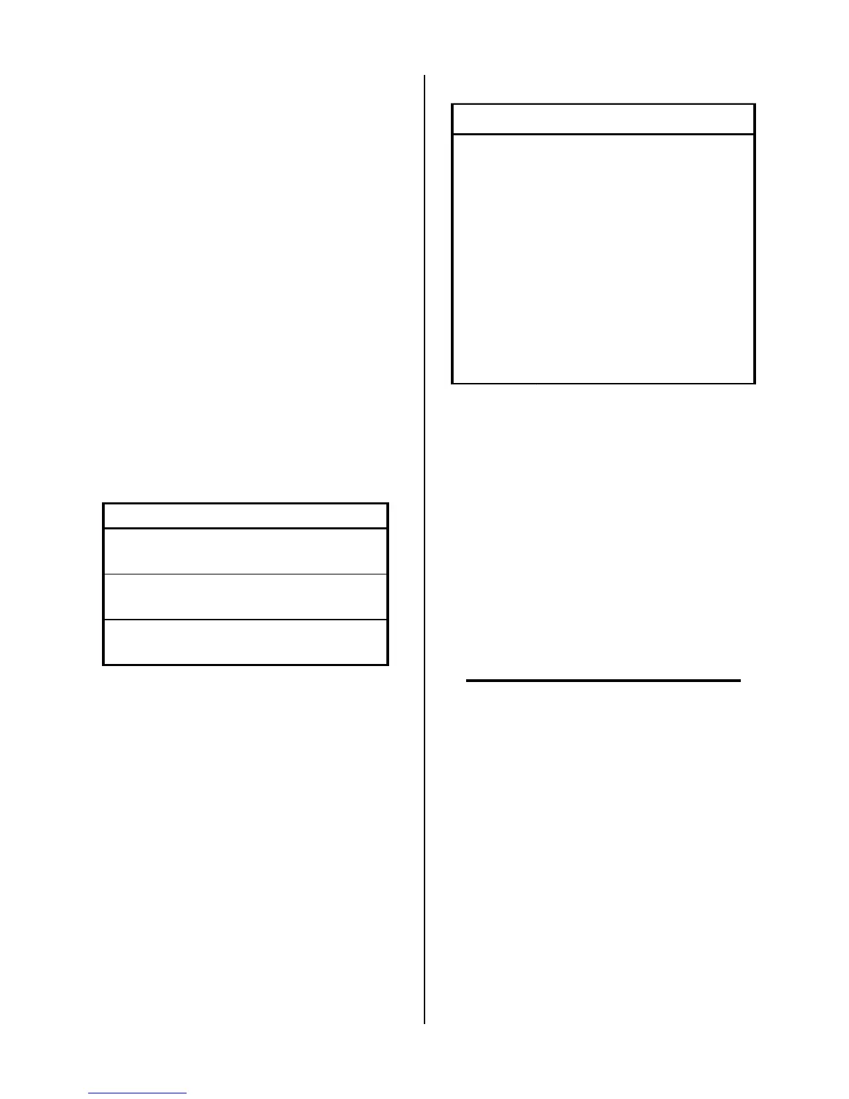
Connection Description of Cable
J9
Ribbon Cable from Logic
PC Board
J8
Ribbon Cable from Top
FET/Heatsink Assembly
J7
Ribbon Cable from Bottom
FET/Heatsink Assembly
4. Remove the four screws securing the Gate Drive
PC Board to the four standoffs.
5. Reinstall the replacement Gate Drive PCB Assem-
bly by reversing the above procedure.
G. FET/Heatsink Assembly Replacement
Follow the anti-static handling procedures in Section 5.02.
1. Remove the Cover per Section 5.04-B.
2. Place the unit on its right side.
3. Remove the Ribbon Cable plug at J6 on the FET/
Heatsink Assembly. To remove the cable, push
down on the locking tab and pull the cable plug
out of the connector.
4. Disconnect all the wire lug connections to the
FET/Heatsink Assembly.
Connection Description
E14 Main Transformer (Primary)
E15 Main Transformer (Primary)
E16 Main Transformer (Secondary)
E17 (-) Output
E18 (+) Output
E19 Main Transformer (Secondary)
E25 (+) From Input Section Assembly
E26 (-) From Input Section Assembly
5. Disconnect the wiring from wire lug connections
on the Capacitor PC Board at '+' and '-' terminals.
6. Remove the two screws securing the Heatsink
Mounting Bracket to the chassis.
7. Lift up on the middle where the two FET/Heat-
sink Assemblies come together and remove the
Mounting Bracket.
8. Slide the FET/Heatsink Assembly out and up to
remove the FET/Heatsink Assembly from the
unit.
9. Install the replacement FET/Heatsink Assembly
by reversing the above procedure.
NOTE
Be sure that the top groove in the FET/Heatsink
Assembly is properly seated over the cutout in the
chassis.
5.07 Rear Panel Parts Replacement
Refer to Section 6.06 for parts list and overall detail draw-
ing.
A. Regulator/Filter Element Replacement
The Regulator/Filter Assembly is on the rear panel. For
better system performance, the Regulator/Filter Assem-
bly filter element should be checked per the Maintenance
Schedule, and either cleaned or replaced. See Section 6,
Parts Lists, for replacement element catalog number.
1. Remove power from the power supply; turn off
the gas supply and bleed down the system.

 Loading...


