REPLACEMENT PROCEDURES 5-6 Manual 0-2725
2. Unscrew the plastic bowl on the bottom of the
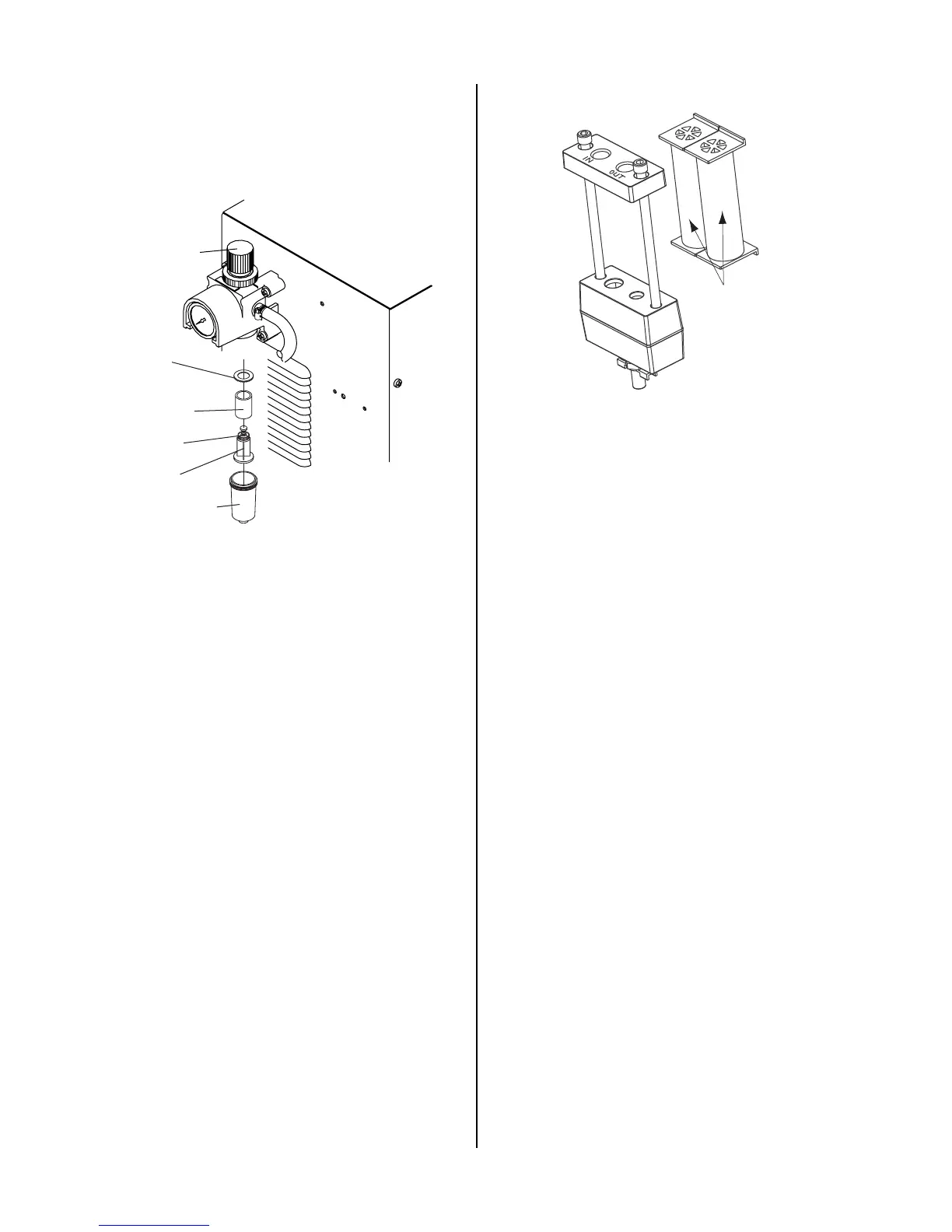
Regulator/Filter Assembly. The filter element
will be visible and still attached to the main body
of the Regulator/Filter.
Regulator/Filter
Assembly
Spool
Plastic
Bowl
Spring
Filter
Element
Baffle
Ring
A-02988
3. Grasp the filter element and unscrew it from the
Regulator/Filter body. The filter element will
come off with a spool and some additional pieces.
4. Note the correct assembly of the filter/spool then
remove the filter from the spool and either clean
it or replace it.
5. The filter element and spool, with the baffle ring
in place (teeth facing downward) can be screwed
back into the Regulator body by compressing the
spring on the spool. Tighten firmly by hand.
B. Two Stage Air Line Filter Replacement
This part is an option and may not be installed on all units.
See Section 6, Parts Lists, for replacement element cata-
log numbers.
Remove power from the power supply; bleed down the
air system.
1. Disconnect the gas supply hose from the IN side
of the Two Stage Filter Assembly.
2. Pull the Two Stage Filter Assembly out of the
mounting bracket.
3. Disconnect the output hose from the OUT side of
the assembly.
4. Install the replacement Two Stage Filter Assem-
bly by reversing the above procedure.
First & Second
Stage
Cartridges
(as marked)
A-02942
C. Pressure Switch Replacement
Remove power from the power supply; bleed down the
air system.
1. Remove the Cover per Section 5.04-B.
2. Disconnect the two wires connected to the Pres-
sure Switch Assembly.
3. Remove the assembly from the T-fitting.
4. Install the replacement Pressure Switch Assem-
bly by reversing the above procedure and noting
the following:
• Apply pipe thread sealant to the fitting before
reassembling.
D. Solenoid Valve Replacement
Remove power from the power supply; bleed down the
air system.
1. Remove the Cover per Section 5.04-B.
2. Disconnect the two wires connected to the Pres-
sure Switch Assembly.
3. Disconnect the two wires connected to the Sole-
noid Valve Assembly.
4. Disconnect the gas tube connected to the bottom
of the T-fitting.
5. Remove the T-fitting and gas fitting from the So-
lenoid Valve Assembly.
6. Remove the Solenoid Valve Assembly from the
straight brass fitting.
7. Install the replacement Solenoid Valve Assembly
by reversing the above procedure.

 Loading...


