SERVICE TROUBLESHOOTING 4-10 Manual 0-2725
C. Diode Testing Basics
Testing of diode modules requires a digital volt/ohmme-
ter that has a diode test scale. Remember that even if the
diode module checks good, it may still be bad. If in doubt,
replace the diode module.
1. Locate the diode module to be tested.
2. Remove cables from mounting studs on diodes to iso-
late the module.
3. Set digital volt/ohmmeter to diode test scale.
4. Using the Figures for each test, check each diode in
the module. Each diode must be checked in forward
bias (plus to negative) and reverse bias (negative to
plus) direction.
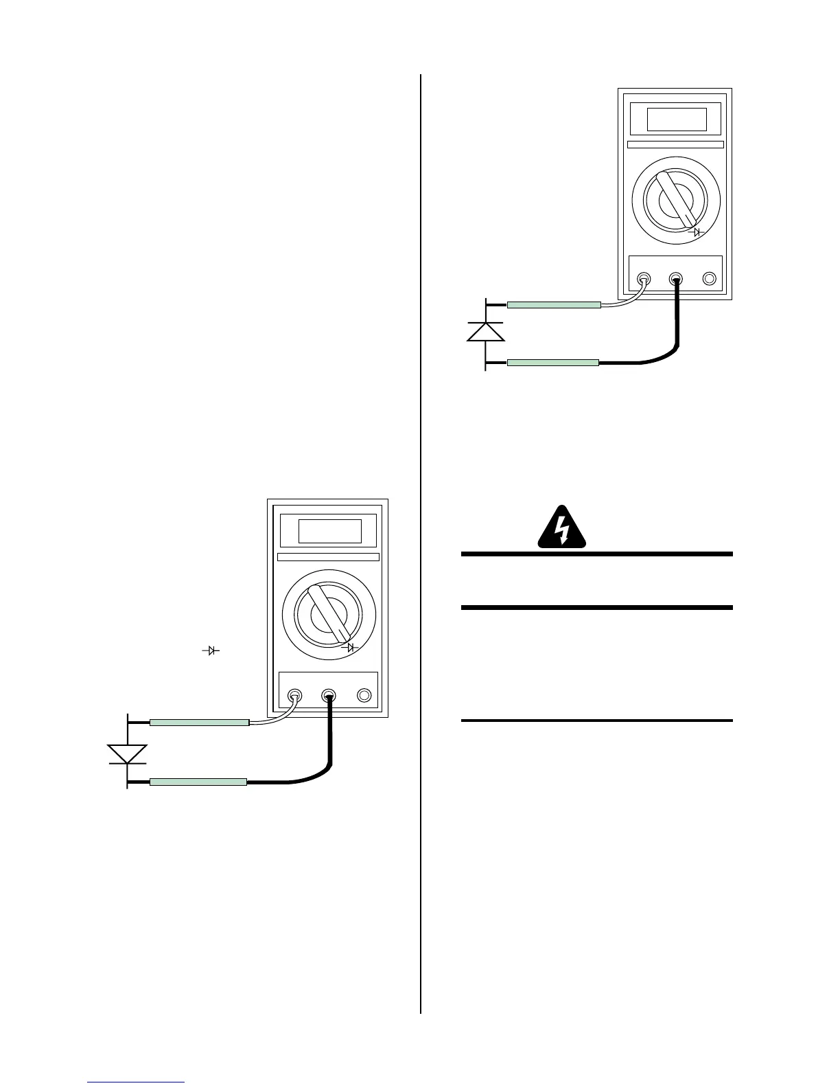
5. Connect the volt/ohmmeter positive lead to the an-
ode (+) of the diode and the negative lead to the cath-
ode (-) of the diode for forward bias testing (refer to
following figure). A properly functioning diode will
conduct in the forward bias direction and indicate be-
tween 0.3 to 0.9 volts.
0.75
VR
COM
A
A-00307
Anode
Cathode
Forward Bias
Diode Conducting
+
_
Diode Test Symbol
Testing Diode Forward Bias
6. Reverse the meter leads across the diode for reverse
bias testing (refer to following figure). A properly
functioning diode will block in the reverse bias direc-
tion and depending on the meter function will indi-
cate an open or “OL”.
7. If a diode checks bad, replace the diode module.
8. Reconnect all cables to proper terminals.
OL
VR
COM
A
A-00306
Anode
Cathode
Reverse Bias
Diode Not Conducting
+
_
Testing Diode Reverse Bias
D. Input Power Checks
This procedure is used to isolate problems that may cause
the main input power disconnect fuses to blow.
WARNING
Place the main input power disconnect to OFF
before disassembly or assembly of any wiring.
1. Place the main input power disconnect to OFF.
2. Remove the wires from the input to the Main Con-
tactor Assembly in the Power Supply. This will
isolate the EMI Filter Assembly.
NOTE
Note the location and label all wires before remov-
ing any wiring.
3. Insulate the ends of the wires with electrical tape
to prevent the ends from contacting each other or
other parts of the Power Supply.
4. Replace main input power disconnect fuses or re-
set circuit breaker.
5. Place the main input power disconnect to ON.
• If main input power disconnect fuse(s) blow
the EMI Filter Assembly is faulty. Replace EMI
Filter Assembly.
• If main input power disconnect fuse(s) do not
blow, proceed to step 6.

 Loading...


