Manual 0-2725 4-15 SERVICE TROUBLESHOOTING
time is over the PWM Enable signal is given and the
DC indicator at the front panel turns ON. When the
pilot arc is established the Pilot On indicator, D33,
turns ON.
If the PWM Enable indicator, D3, does not come ON
then replace the Logic PCB.
If the PWM Enable indicator, D3, turns ON then OFF
immediately, the following test should be performed:
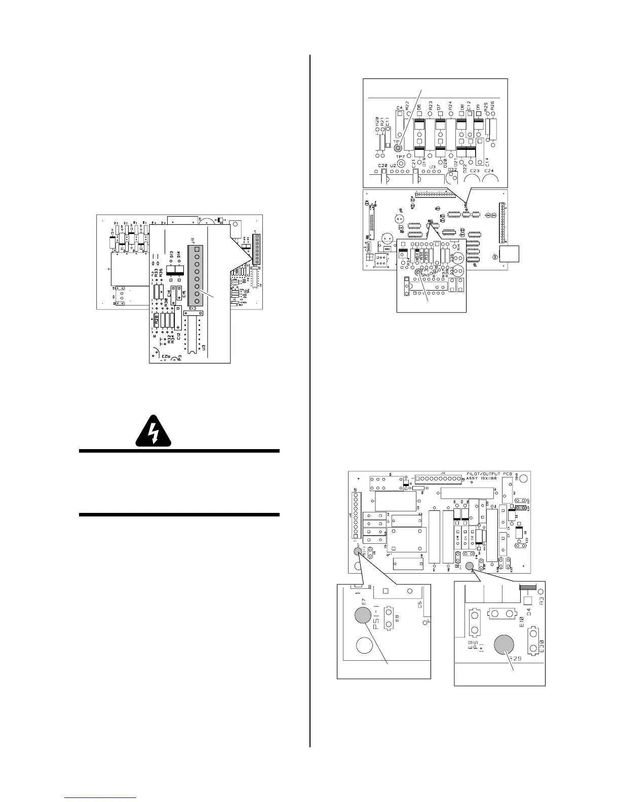
a. Disconnect J11 from the CD PC Board to dis-
able the CD signal.
A-01202
J11
CD PC Board
b. Connect a jumper between TP1 and TP8 on
the Logic PC Board in the unit. This will cause
the gas to flow continuously.
WARNING
Connector J11 on the CD PC Board must be dis-
connected to prevent electrical damage to measur-
ing equipment when testing the open circuit volt-
age (OCV).
TP8
A-01737
TP1 (GND)
c. Press and hold the hand torch switch (Logic
PC Board Torch Switch Enable indicator, D5,
turns ON).
d. Measure open circuit voltage between E29 (+)
to E7 (-) at the Pilot Output PC Board. If volt-
age is low, each FET/Heatsink Assembly
should be tested individually.
A-01401
Pilot Output PC Board
E29
E7
Top

 Loading...


