Manual 0-2725 4-17 SERVICE TROUBLESHOOTING
A-01215
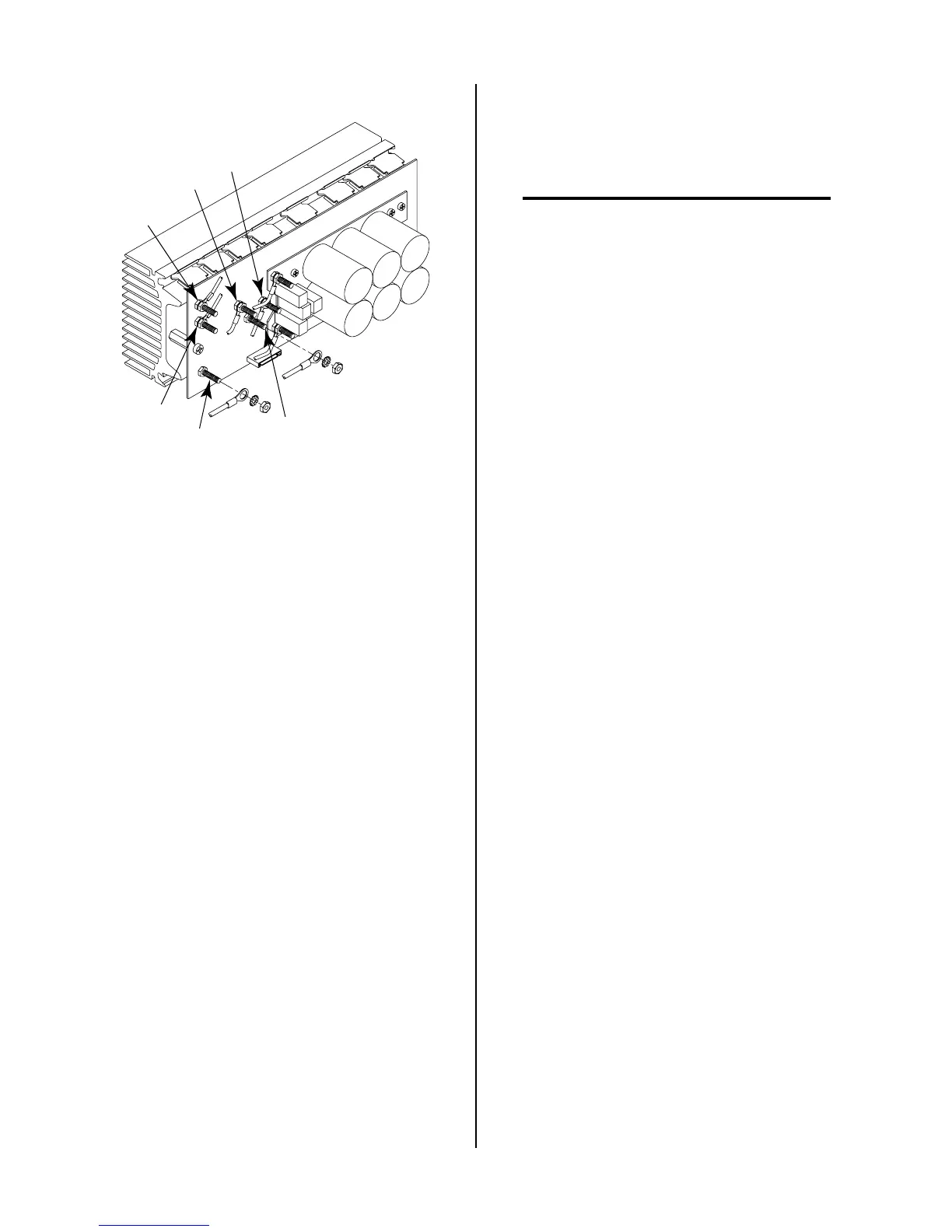
E16
E18
E19
E17
E14
E15
b. Place the meter (+) lead on E16 and the meter (-)
lead on E18 of the FET/Heatsink Assembly to
check the output rectifier forward bias. The meter
should indicate between 0.3 to 0.6 volts using the
diode function or 100K ohms using the ohms func-
tion.
c. Place the meter (+) lead on E18 and the meter (-)
lead on E16 of the FET/Heatsink Assembly to
check the output rectifier reverse bias. The meter
should indicate 'OL' using the diode function or
100K ohms using the ohms function.
d. Place the meter (+) lead on E17 and the meter (-)
lead on E19 of the FET/Heatsink Assembly to
check the output rectifier forward bias. The meter
should indicate between 0.3 to 0.6 volts using the
diode function or 100K ohms using the ohms func-
tion.
e. Place the meter (+) lead on E19 and the meter (-)
lead on E17 of the FET/Heatsink Assembly to
check the output rectifier reverse bias. The meter
should indicate 'OL' using the diode function or
100K ohms using the ohms function.
f. Place the meter (+) lead on E18 and the meter (-)
lead on the heatsink of the FET/Heatsink Assem-
bly to check the output rectifier resistance to
ground. The meter should indicate >1 meg ohms.
Replace the FET/Heatsink Assembly if any of the
above tests are open or shorted.
6. FET Output Clamp Diodes Check
Use an ohmmeter to check the resistance of the out-
put clamp diodes, (+ out) E17 and (- out) E18, per the
following procedure:
NOTE
The wires on E16 and E18 should still be discon-
nected from both FET/Heatsink Assemblies.
a. Place the meter (+) lead on E17 and the meter (-)
lead on E18 of the FET/Heatsink Assembly to
check the output clamp diode resistance. The
meter should indicate >1 meg ohms.
b. Place the meter (+) lead on E18 and the meter (-)
lead on E17 of the FET/Heatsink Assembly to
check the output clamp diode resistance. The
meter should indicate >1 meg ohms.
Replace the FET/Heatsink Assembly if any of the
above tests are open or shorted.

 Loading...


