CUTMASTER 60i
Manual 0-5475 SERVICE
5-9
Resistance and Diode Tests
The following tests require a meter with both a resistance (ohms), preferable X1, scale and diode measuring scale.
You need to become familiar with how your meter measures diodes. Most meters apply a positive voltage on the +
or red lead. I will refer to + and – leads. For + use whichever color your meter applies the + voltage.
Diodes will conduct in one direction, referred to as the “forward” direction and show an open or high resistance
in the reverse direction.
0.75
VR
COM
A
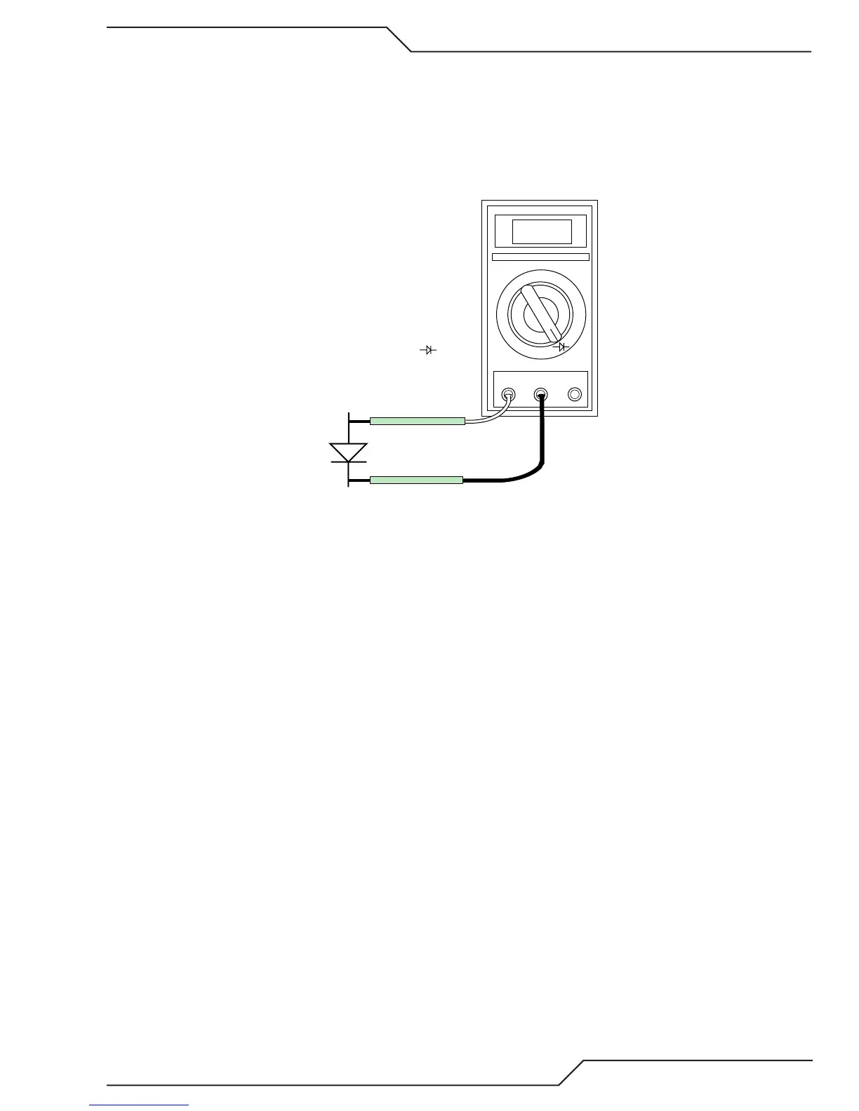
Anode
Forward Bias
Diode Conducting
+
_
Diode Test Symbol
You need to be familiar with how your meter reads the forward direction of a diode on the diode measuring scale.
Some digital meters such as Fluke show a voltage, usually 0.3 to 0.5V for forward resistance of a power diode such
as we will be measuring here. I will refer to this measurement as resistance/voltage to cover either type of meter.
Smaller diodes usually read a little higher, perhaps 0.6-0.7V. Whatever your meter reads for one diode in the forward
direction expect twice that for two diodes in series.
When measuring diodes connected to capacitors, as many of these are, the reverse direction may show a low re-
sistance/voltage at first but the reading gradually rises as the capacitor charges. Reversing the meter will slowly
discharge the capacitors, reading going down, then increasing in the opposite direction until the value stabilizes.
Let the reading come to a stable value or go off scale before you decide what the actual reading is.