CUTMASTER 60i
Manual 0-5475 OPERATION
4-1
SECTION 4 SYSTEM:
OPERATION
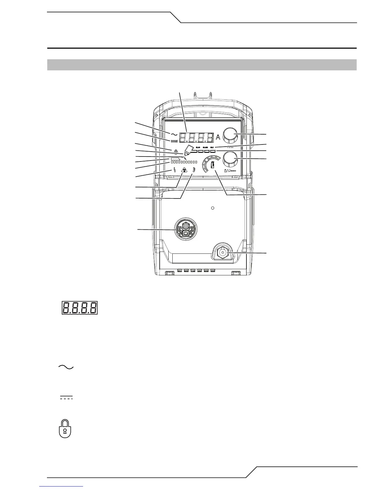
4.01 Front Panel Controls / Features
See Illustration for numbering Identification
1
2
3
4
5
6
7
8
9
10
11
12
13
14
15
16
17
18
Art # A-13250
1. Numeric Display
• Displays software revision at start up
• Displays amperage values (Factory default)
• Displays error codes
• Displays pre-set (preview) maintenance functions
2. AC Indicator
Steady light indicates power supply is ready for operation. Blinking light indicates the input voltage is outside
of operating range or internal fault.
3. DC Indicator
Indicator is ON when DC output circuit is active.
4. Latch/Lock
Indicator is ON when unit is in "Latch" mode.