CUTMASTER 60i
INSTALLATION Manual 0-5475
3-2
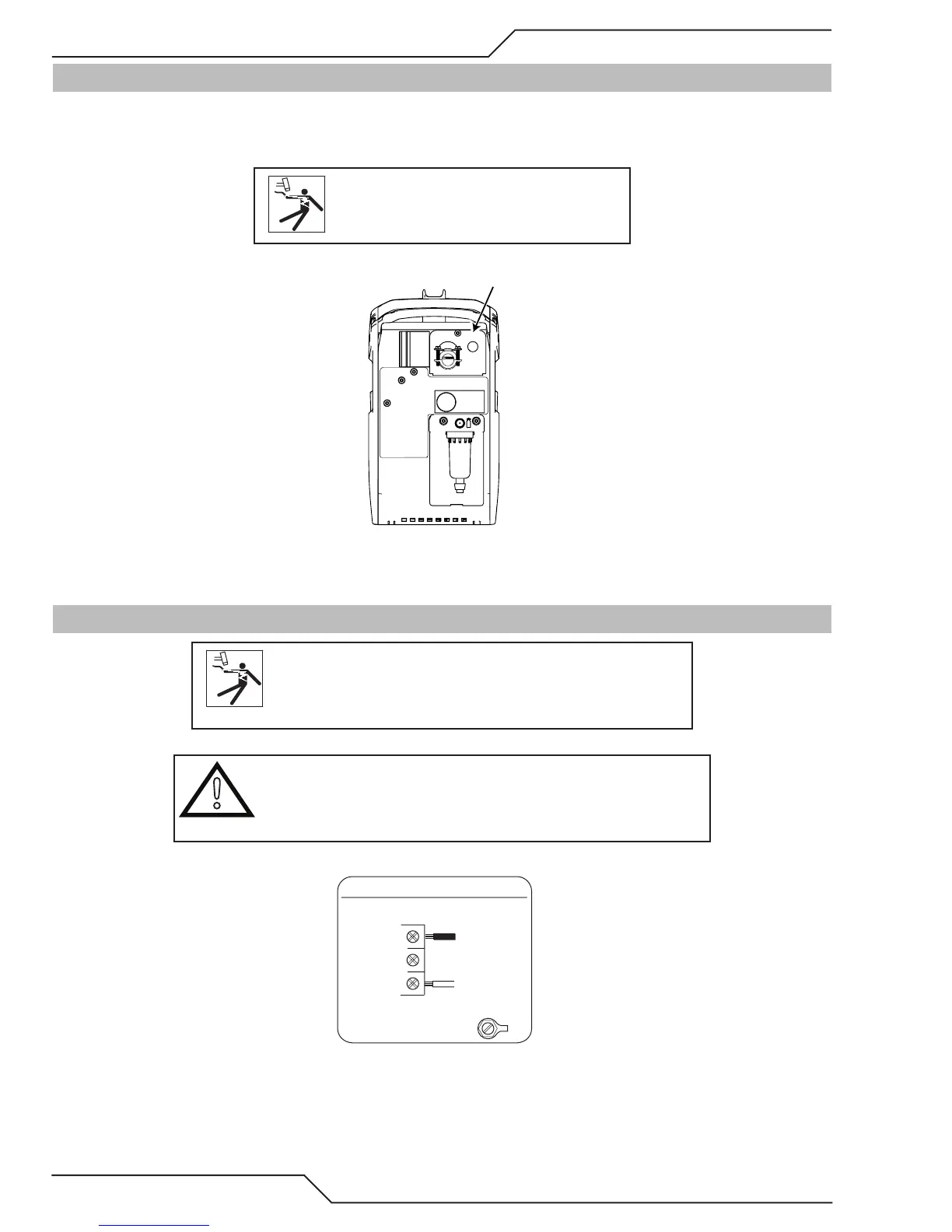
3.03 Opening the Main Switch Cover
Systems are configured for and come with power cord connected for single phase or three phase configuration
depending on system purchased. The input power switch is located on the rear panel along the top. To access the
input locations, remove the screw at the top of the cover and flip down.
CAUTION
Disconnect power before removing the
cover.
Main Switch Cover
3.04 Primary Input Power Connections, SINGLE Phase
WARNING
Each CutMaster 60i system is a dedicated 1 Phase OR 3 Phase
system and cannot be reconfigured to the other. Personal injury
could occur if changing the phase is attempted..
CAUTION
The primary power source, fuse, and any extension cords used must
conform to local electrical code and the recommended circuit protec-
tion and wiring requirements as specified in Section 2.
Line
GND
Single-Phase (1ø)
Power Cord
Power Switch
Single Phase Input Power Wiring