EasyManuals Logo

Thermal Dynamics CUTMASTER 60i Service Manual

Thermal Dynamics CUTMASTER 60i
104 pages
To Next Page IconTo Next Page
To Previous Page IconTo Previous Page
Page #73 background imageLoading...
Page #73 background image
CUTMASTER 60i
Manual 0-5475 SERVICE
5-39
5.12 Internal Parts Replacement
Cover Removal
WARNING
Disconnect primary power to the system
before disassembling the torch, leads, or
power supply.
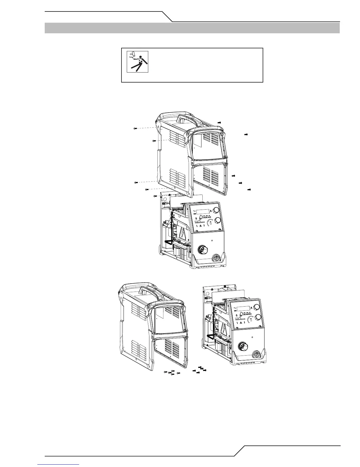
1. Remove input power from the system then remove the ten, M5x0.8x16mm hex screws (5 on each side) that
secure the cover assembly to the power supply. Do not remove the screws securing the handles to the cover.
Art # A-13308
2. Carefully lift cover up and away. All handles and side bezels should be connected to the cover.
Art # A-13309
Proedure is now complete.

Table of Contents

Other manuals for Thermal Dynamics CUTMASTER 60i

Questions and Answers:

Question and Answer IconNeed help?

Do you have a question about the Thermal Dynamics CUTMASTER 60i and is the answer not in the manual?

Thermal Dynamics CUTMASTER 60i Specifications

General IconGeneral
BrandThermal Dynamics
ModelCUTMASTER 60i
CategoryWelding System
LanguageEnglish

Related product manuals