Manual 0-2569 51 REPLACEMENT PROCEDURES
A. Power Driver PC Board Kit Replacement
The Power Driver PC Board Replacement Kit is a di-
rect parts replacement for the failed Driver PC Board
and Switching Transistor (Q1) Assemblies in the
Power Supply.
WARNING
Disconnect primary power at the source before as-
sembling or disassembling power supply, torch
parts, or torch and leads assemblies.
1. Turn OFF main input power to the Power Supply
both at the Power Supply ON/OFF switch and at
the main power disconnect.
2. Wait at least two minutes to allow the input ca-
pacitors to discharge.
3. Remove the top panel of the Power Supply. To
remove the top panel of the Power Supply requires
the removal of several phillips head screws. Care-
fully remove all the screws before attempting to
remove the top panel.
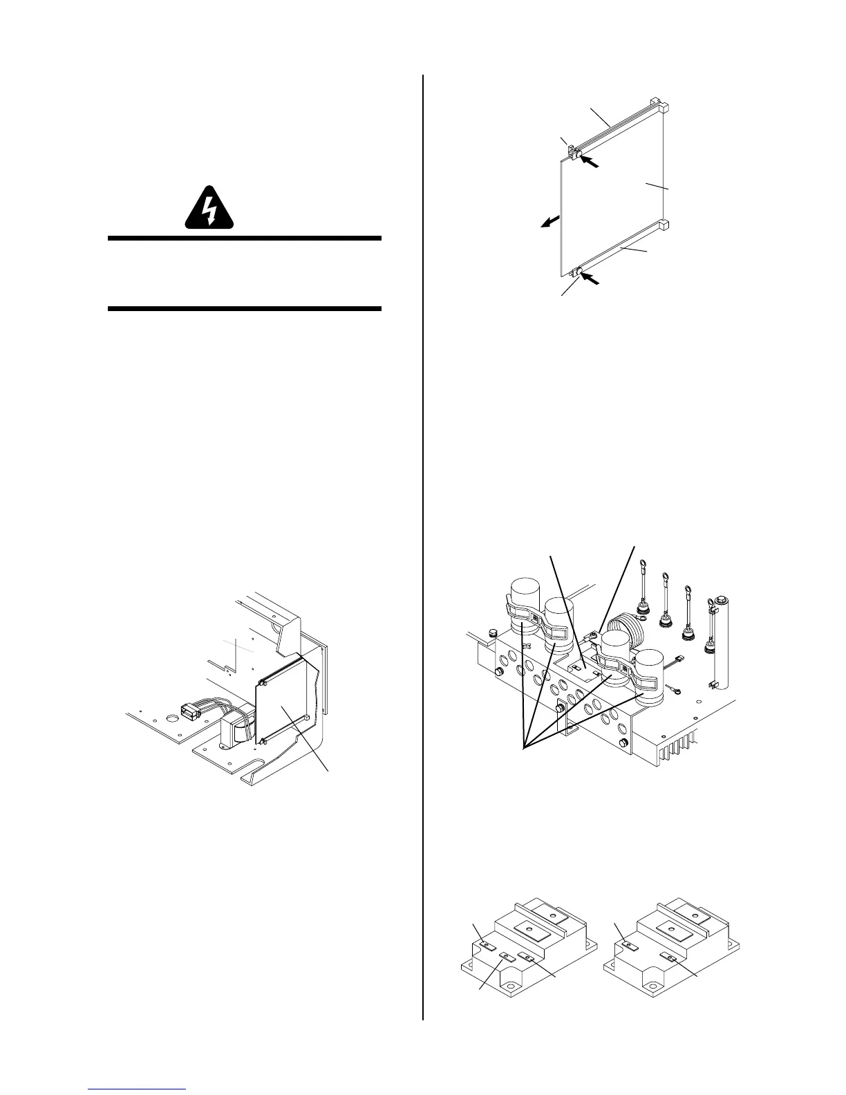
4. Locate the old Driver PC Board Assembly on the
inside left side, behind the front panel, as viewed
from the front of the unit.
Driver PC Board
Rear of Front Panel
A-01083
5. Note and label the two wiring connectors that con-
nect to the Driver PC Board.
6. Disconnect the two wiring connectors from the
Driver PC Board.
7. Press in the securing tab knob on the PC Board
Guide to release the PC Board from the PC Board
Guides. There is a securing tab on both the upper
and lower PC Board Guides.
Upper PC Board Guide
Lower PC Board
Guide
Securing Tab
Securing Tab
Driver PC
Board
A-01084
8. Carefully pull the PC Board from the guides and
remove from the unit.
9. Install the replacement Driver PC Board Assembly
reversing the above procedure.
10. Locate the old Switching Transistor (Q1) Assem-
bly on the inside center-left, between the four large
blue capacitors, as viewed from the front of the
unit.
Switching Transistor
Q1
Large Blue
Capacitors
A-01085
Transistor/Coil
Bracket
11. There are two different styles of the Switching
Transistor (Q1). The style can be identified by look-
ing at the top of the transistor casing.
Style With 'E' Terminal
Style Without 'E' Terminal
BX
B
E
BX
B
A-01088
 Loading...


