REPLACEMENT PROCEDURES 52 Manual 0-2569
12. Note and label the wires connected to the Switch-
ing Transistor Assembly.
NOTE
The older style transistor will have two wire con-
nections to the transistor module and the newer
style will have only one wire connections.
13. Remove the two screws securing the wires to the
Switching Transistor Assembly terminals 'E' and
'B'.
14. Remove the screw that secures the Capacitor
Mounting Bracket to the Switching Transistor As-
sembly
15. Remove the screw that secures the Transistor/
Coil Bracket to the Switching Transistor Assem-
bly.
16. Remove the screw and washer securing the PTC
Resistor Assembly to the Main Heatsink. Move
the PTC Resistor Assembly out of the way to pre-
vent it from becoming damaged.
PTC Resistor Assembly
Q1
Main Heatsink
A-01089
17. Remove the four screws securing the Switching
Transistor module to the Main Heatsink.
18. Pry between the Main Heatsink and the faulty
Switching Transistor Assembly until it slides eas-
ily (see NOTE)
NOTE
DO NOT scratch the Heatsink surface under the
Transistor Assembly.
19. Remove the faulty Switching Transistor Assem-
bly from the unit by sliding it towards the center
of the Main Heatsink.
CAUTION
DO NOT damage Heatsink.
20. If the transistor thermstrate was not removed with
the transistor, it must be removed.
21. Clean the old transistor thermstrate from the tran-
sistor mounting area. Verify that the Heatsink sur-
face under the transistor is smooth and free of de-
fects.
22. Install the replacement Transistor Thermstrate and
the Switching Transistor Assembly by reversing
the above procedure and noting the following:
• Place the replacement Transistor Thermstrate
onto the Main Heatsink at the Switching Tran-
sistor mounting location.
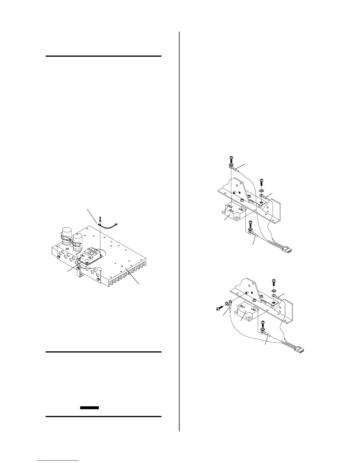
• Depending on the style of the replacement
Switching Transistor connect the wires per one
of the following Figures:
B
BX
Wire #83
Wire #82
Wire #84
Q1
E
A-01086
Wire Connections (Q1 With E Terminal)
B
BX
Wire #83
Wire #82
Wire #84
Q1
A-01087
Wire Connections (Q1 Without E Terminal)
• The metric screws supplied with the Switching
Transistor are to be used for the transistor wire
connections. Small metric screws are to be
torqued to 12 in-lbs (1.4 Nm). Larger metric
screws are to be torqued to 26 in-lbs (2.9 Nm).
 Loading...


