23
.....Additional setup menus within the CALIBR submenu
Zero flow set method continued
After the instrument is properly zeroed, it should display a stable reading well below 0.05 ft/s (0.015 m/s)
under zero flow conditions with the low flow cutoff disabled.
Prior to performing a zero set calibration, verify the following:
1. Transducers are connected to the pipe.
2. Instrument is reading flow.
3. Low flow cutoff is disabled to allow verification of calibration.
A. Zero Flow Set Method
The best method of zeroing the instrument is to stop the flow and perform a zero flow set on the pipe. The
purpose of the zero flow set is to zero the instrument for the individual application. This method is used
only when flow in the pipe can be stopped. The flow rate displayed in Menu 01 must be between -0.25 and
+0.25 ft/s (-0.076 and +0.076 m/s).
1. Ensure there is no flow in the pipe.
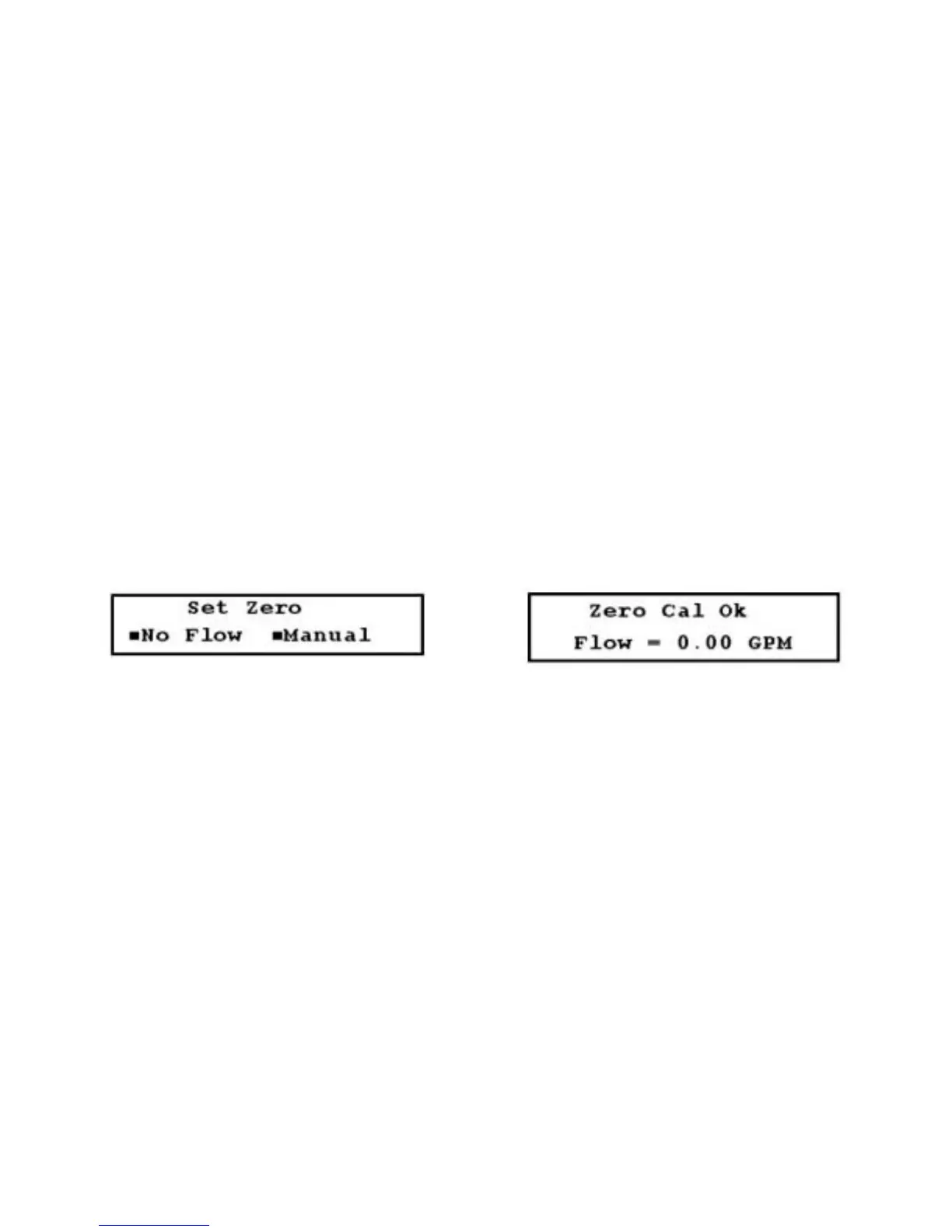
2. Access Menu 51 (Figure 3.13-B, below).
3. Select No Flow. If the zero flow set calibration is successful, Figure 3.13-C (below) is displayed.
FIGURES 3.13-B (LEFT) & 3.13-C (RIGHT)
B. Manual Zero Set
Use this method infrequently. Manual zero set applies a constant offset entered by the user to all readings.
For example, if the flow reads 250 GPM and a 10 GPM offset is applied, the new reading becomes 240
GPM. To zero the instrument using the manual zero set method:
1. Minimize flow occurring in the pipe.
2. Access Menu 51 and select Manual. Figure 3.13-D (page 24) is displayed.
3. Enter the value of the required offset and press ENTER. If necessary, you can apply a negative offset
by pressing ± (plus/minus key).
The flowmeter is now calibrated with the manual zero set method, and the zero point offset is displayed
(Figure 3.13-E, page 24).