37
.....Spacing & mounting the transducers
8. Continued
a. Refer to Figure 1.6 (page 5) to locate the upstream and downstream connectors on the side of
the meter.
b. The upstream transducer cable has red-banded ends, and the downstream transducer cable has
blue-banded ends (Figure 4.3-B, page 36).
9. If maximum accuracy at low flow rates is important, calibrate the flowmeter according to Section 3.13
(page 22). The flowmeter is now capable of accurately measuring velocity and flow.
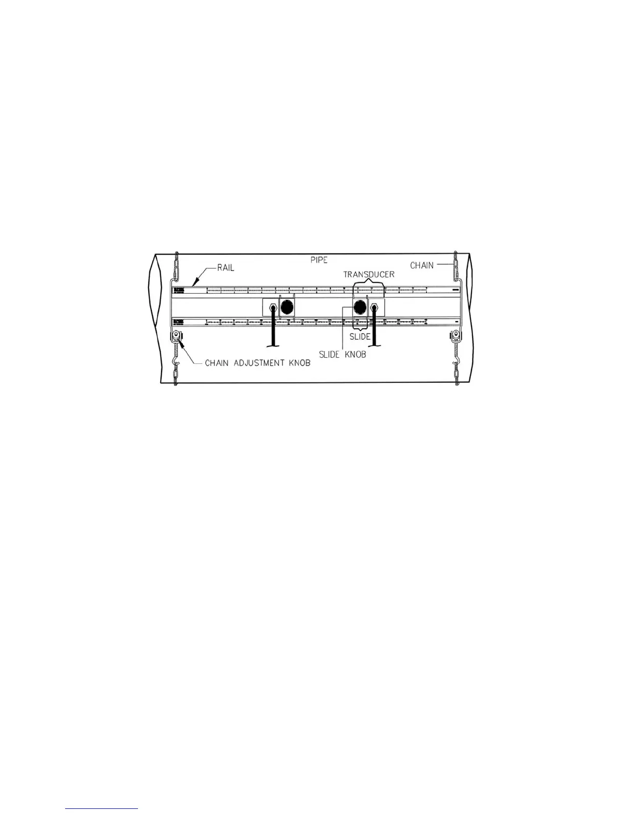
FIGURE 4.3-C: PORTABLE TRANSDUCER RACK INSTALLATION
4.4 Transducer Mounting Methods
There are several methods of mounting the transducers. The best method is determined by the specific
application. Complete steps 1-5 in Section 4.3 (page 35), and refer to the following sections for instructions
on how to properly mount the transducers with one of the available mounting methods.
4.4.1 V Method
The V method (Figure 4.4-A, page 38) is considered the standard method for pipes with 4- to 16-in (101.6
to 406.4 mm) diameters. This method typically yields a more accurate reading than the Z method since it
utilizes a longer measurement path.
Ensure V is the selected mounting method.