33
4. WIRING & INSTALLING THE TRANSDUCERS
4.1 Wiring
The transducer terminals and cables are arranged in pairs and are labeled DN STREAM and
UP STREAM. The downstream transducer cable has blue-banded ends; the upstream transducer has
red-banded ends.
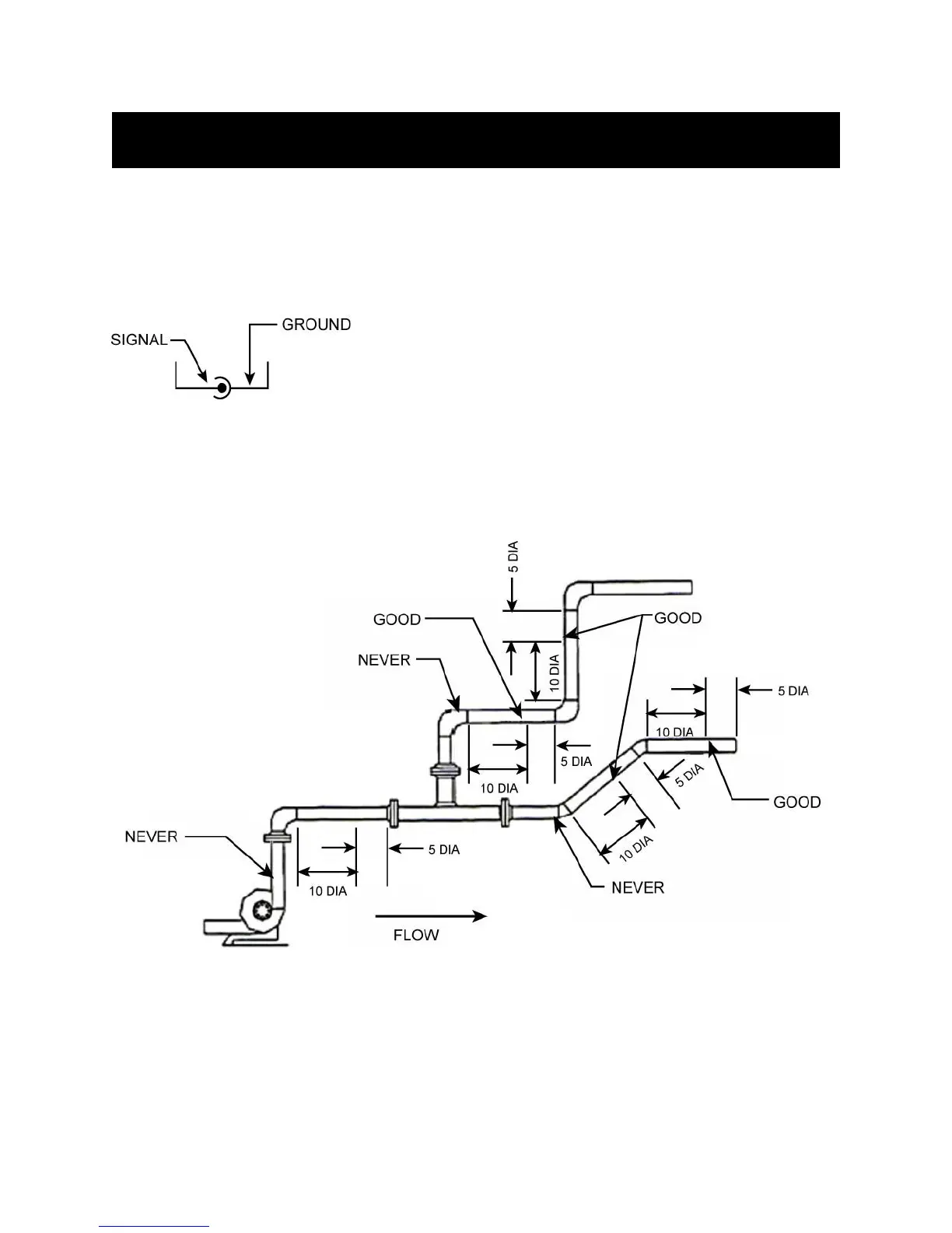
FIGURE 4.1
Locate the symbol seen in Figure 4.1. This symbol is on both pairs of
terminals and indicate which terminals should connect to the center
wire conductors and which should connect to the coaxial shields.
4.2 Site Selection & Preparation
Prior to installing the transducers, a proper site must be selected to ensure accurate measurement.
Examples of site recommendations are illustrated in Figures 4.2-A (below) and 4.2-B (page 34).
FIGURE 4.2-A