43
.....Small pipe applications
FIGURE 4.5-A
For high temperature or outdoor small pipe applications, use the foam tape strips shipped with the
flowmeter to block the side wave paths. Other tape materials generally do not satisfy performance or
safety specifications. Please contact Thermo when more tape strips are needed.
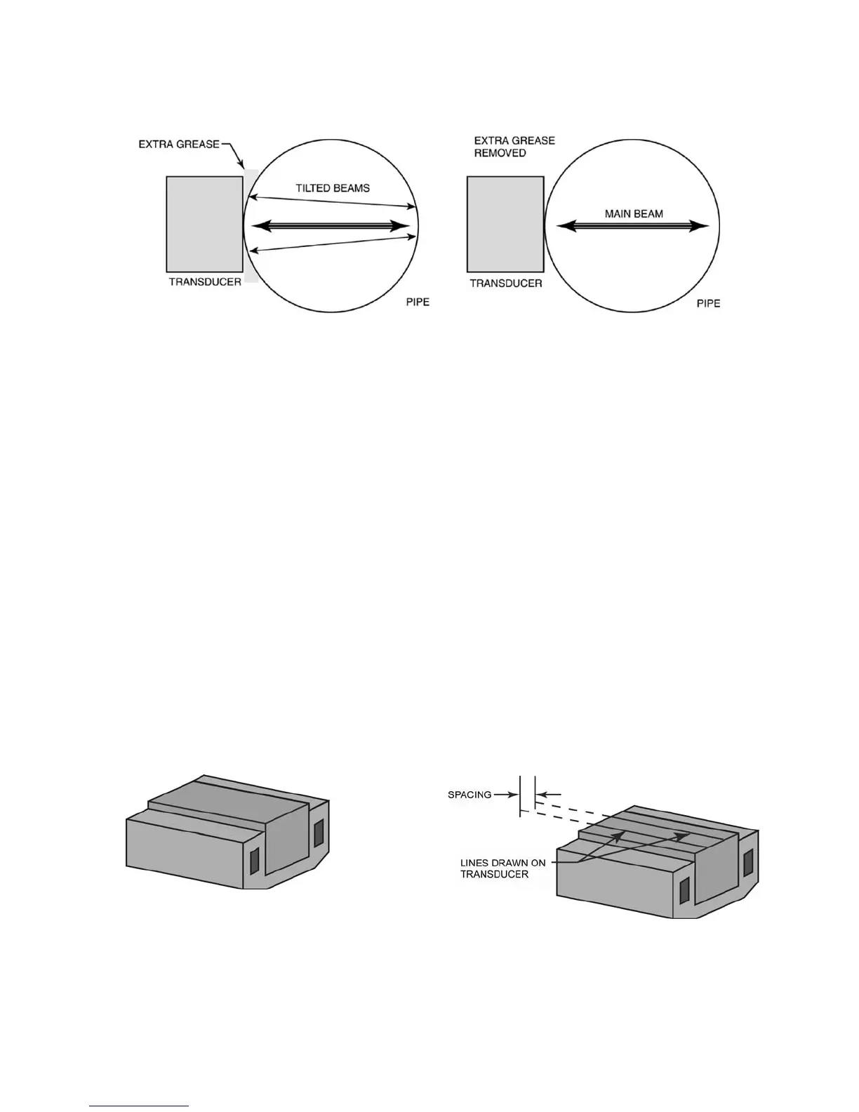
1. Wipe grease off the coupling surfaces of both transducers. Clean the surfaces with detergent and let
dry (Figure 4.5-B, below).
2. Refer to Figure 4.5-C (below) and draw two lines on each transducer surface with a pencil so that the
band defined by the lines is in the middle of the surface. The spacing between the two lines should be
as follows:
a. 3.0 to 3.5 in pipes: 0.50 in (76.2 to 88.9 mm pipes: 12.7 mm)
b. 2.5 to 3.0 in pipes: 0.44 in (63.5 to 76.2 mm pipes: 11.2 mm)
c. 2.0 to 2.5 in pipes: 0.38 in (50.8 to 63.5 mm pipes: 9.7 mm)
d. 1.5 to 2.0 in pipes: 0.32 in (38.1 to 50.8 mm pipes: 8.13 mm)
e. 1.5 in and smaller pipes: 0.25 in (38.1 mm and smaller pipes: 6.35 mm)
3. Remove the adhesive protection paper to expose the tape strips. Place a strip on each side of the
surface along the line. Press the strips down to ensure good adhesion (Figure 4.5-D, page 44).
4. Apply coupling compound to the space between the tape strips. The optimum height of the compound
layer is approximately one-half the height of the tape strips (Figure 4.5-E, page 44).
FIGURES 4.5-B (LEFT) & 4.5-C (RIGHT)