1-26
Before disassembling the hydraulic control valve, clean
the body with a suitable solvent and dry with compressed
air.
Ensure all openings are plugged to prevent solvents and
dirt from contaminating the control valve assembly. Refer
to diagram C2776, pg. 1-25, to assist in the disassembly
of the control valve.
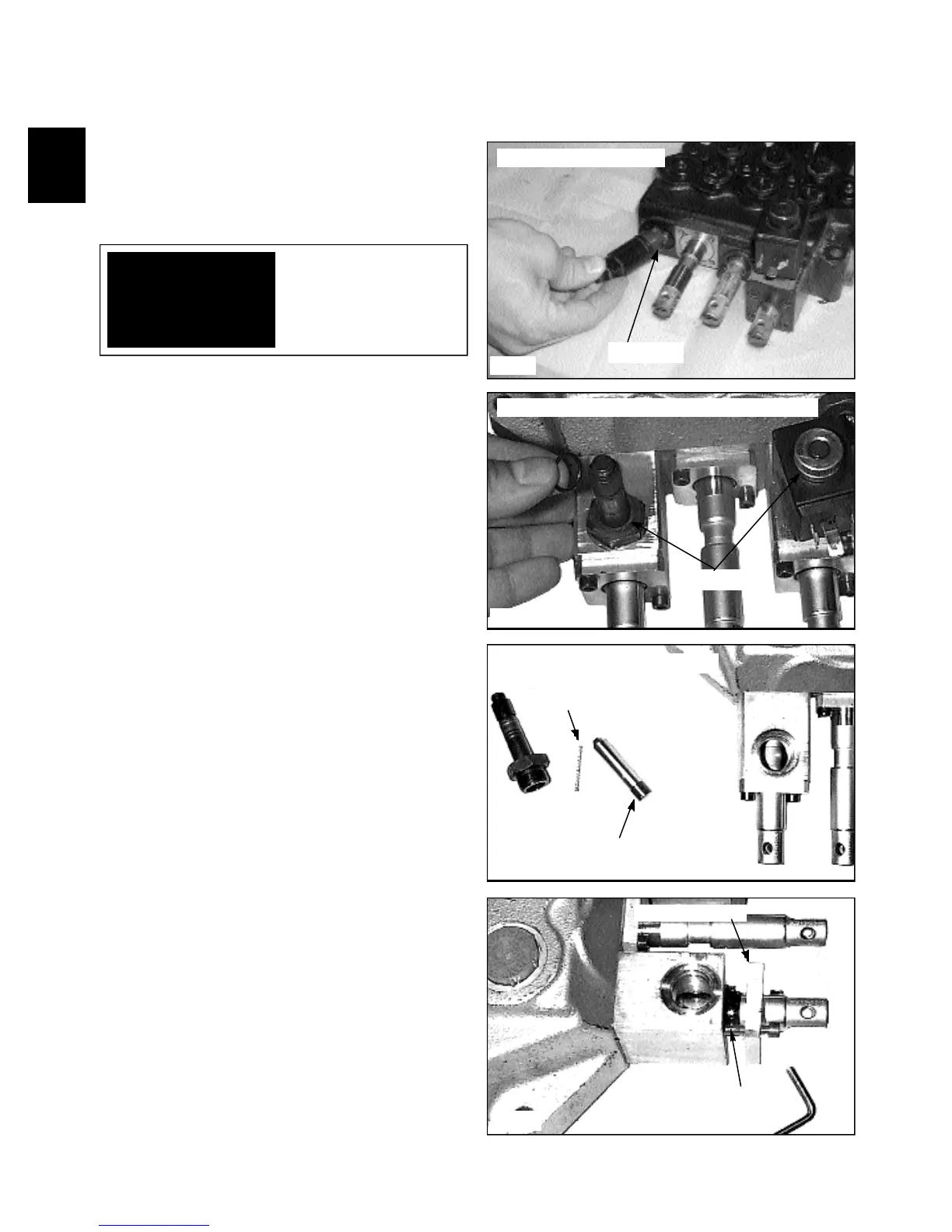
1 Remove the pressure relief valve. Discard the O-
rings (fig. C2975).
WARNING
To avoid eye injury, use
safety goggles when clean-
ing with compressed air.
Removing the relief valve
Removing the solenoid coils from the spool locks
Removing the lock from the valve
CONTROL VALVE 1.3
C2975
C2235
C2236
C2244
3 Remove the outer wiper seal cover from the lock
block. (fig. C2244)
2 Remove the solenoid coils and locking pin from the
valve lock block. (fig. C2235, C2236) There are 2 O-ring
seals located on either side of the solenoid coils.
O-ring seal
Spring
Lock pin
Wiper seal cover
Wiper seal
Disassembly / Repair
O-ring seal