2-38
DRIVE MOTOR 2.12
C2305
C2304
C2306
C2307
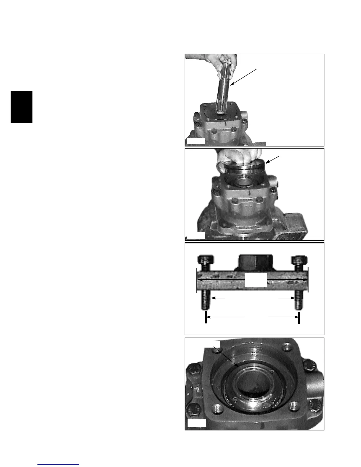
15 Remove the cardan (drive) shaft (fig. C2304).
16 Remove the intermediate spacer (fig. C2305) .
Replace the seal with new item at time of assembly.
Disassembly (cont’d)
Cardan shaft (drive)
Intermediate spacer
Special tool
Bearing nut
2.4 in.
(60 mm)
3 in.
(76mm)
6mm machine screws
17 A special tool will be required as shown in fig.
C2306 to remove the bearing nut (fig. C2307). Tool
shown was made using 1/2 in. X 1 in. X 3 in. long
(12mm x 25mm x 76mm L) material. Two holes were
drilled and tap 60mm apart, to accept 6mm X 30mm
machine screws.