2-29
DRIVE MOTOR 2.11
Removal
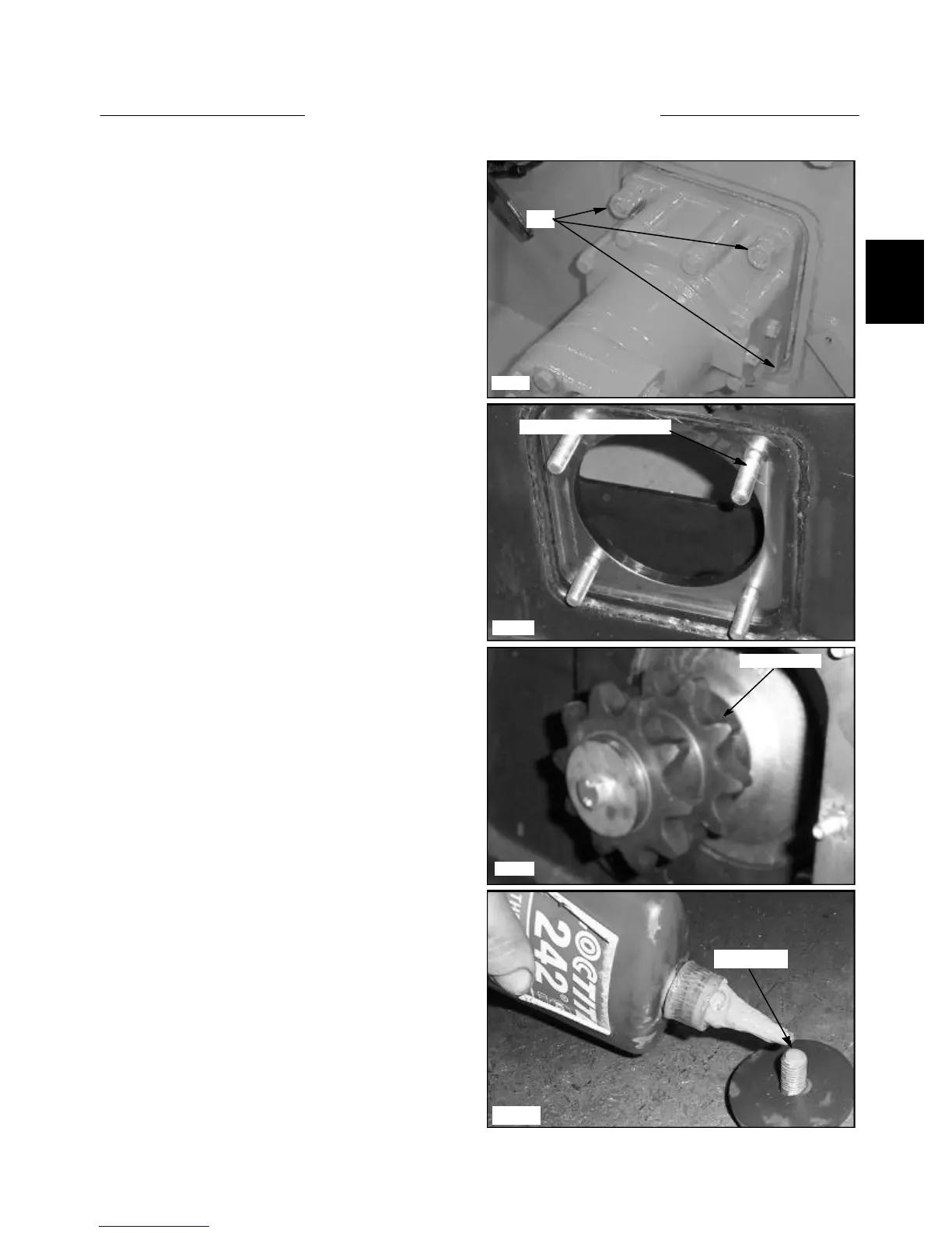
12 Remove the jam nuts, mounting nuts and lock wash-
ers from the 4 mounting bolts retaining the drive motor to
the final drive housing. (fig. C3491) Hold the head of the
bolts from inside the final drive housing. (fig. C3492)
13 Remove the drive motor. Seal the drive motor with
silicone upon reassembly.
14 Upon reassembly torque the 4 mounting nuts to 80
lbs / ft.
15 If the drive motor replacement is being performed
because of major parts failure, such as geroter damage,
the hydraulic system must be checked for contamination
and flushed if necessary as outlined in Section 2.7.
C3491
Nuts
C3767
C3493
Apply loctite
C3492
Torque motor mounting bolt
Drive sprocket
17 Install the sprocket, machined washer, lock washer
and bolt. Apply Loctite 242 (blue) to the threads of the
bolt before torquing (fig. C3767) and torque the bolt to 40
lbs / ft. (54 nm).
16 If you are installing a new drive motor, remove the
drive motor sprocket and bolt if you wish to reuse the
sprocket. (fig. C3493)