© 2020 Thorlabs GmbH20
DC2200
Note
The frequency range of the modulating TTL signal is measured under the following definitions
and conditions:
· Resistive load
· The "Maximum Modulation Frequency"
f
max
is defined as the frequency, when the sum of
rise time
t
rise
and fall time
t
fall
equals 10 % of the TTL signal period:
· Rise and fall time are defined as the time between 10% and 90% of the current at TTL
HIGH level
Max. Modulation Frequency
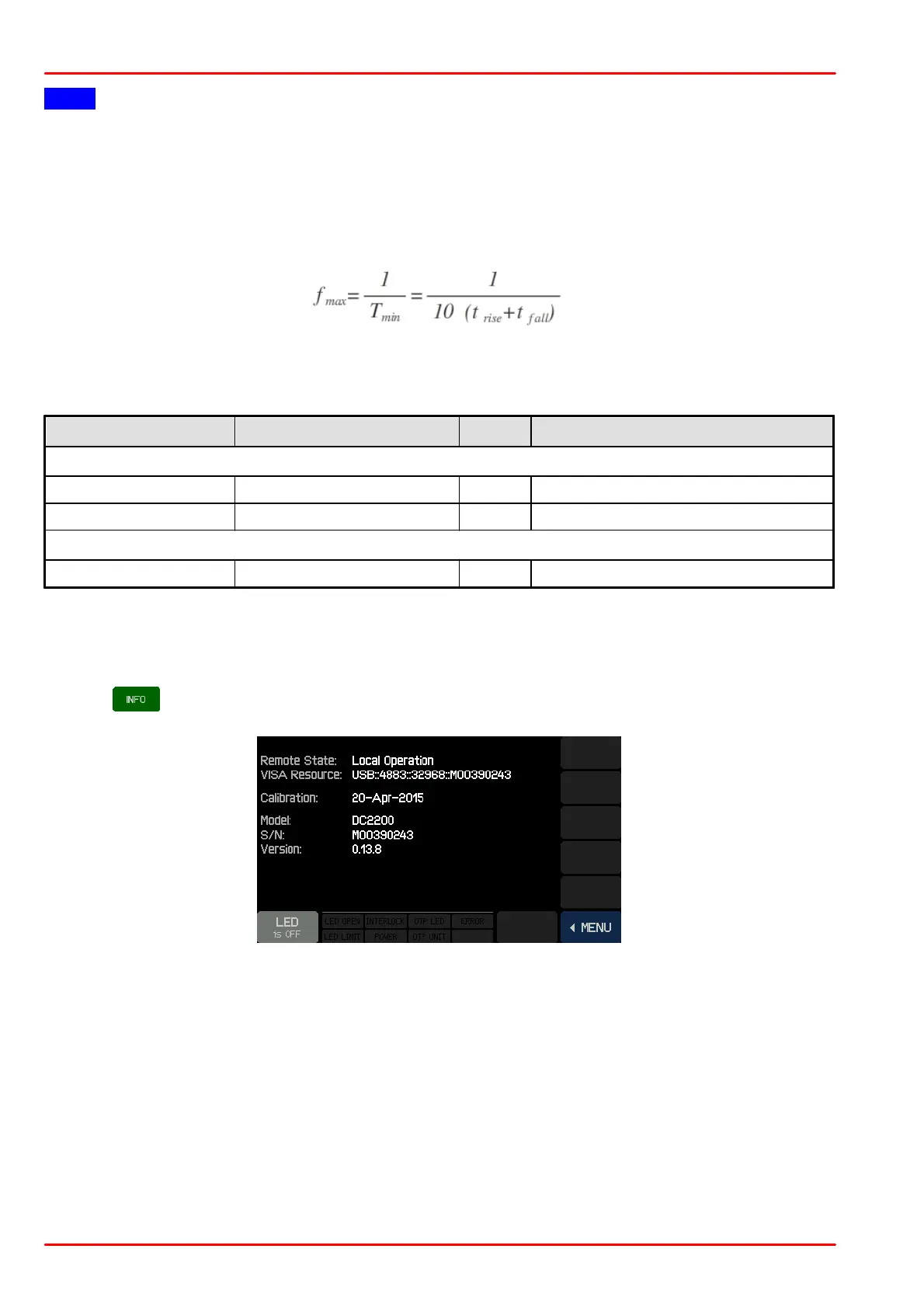
3.3.8 Info
Tap the button to display information about the DC2200 hardware and firmware: